Switch settings
Reference for the embedded switching features of ReadyLinks devices, covering device-wide security and services, virtual interface settings and per-port settings, with CLI examples.
This guide describes the embedded switching features of ReadyLinks devices. Settings are grouped into system management, device-wide switch settings, virtual interface settings, VLANs, layer 2 switching, access security, per-port settings, QoS, monitoring and G.hn settings.
#System management
#CLI access and user levels
Every ReadyLinks switch can be managed from a command-line interface (CLI) using the console port, Telnet, or SSH. The CLI is organized into views: the top-level system view (#), the global configuration view ((config)#, entered with configure terminal), and feature views such as a port ((Ghn1)#), a VLAN ((vlan10)#), or 802.1X ((dot1x)#). Type end or press Ctrl+Z to return to the system view.
Type ? at any prompt to list the commands available in that view, or after a partial command to list the remaining keywords. Press Tab to auto-complete a keyword. CLI changes take effect immediately; run write to save them to the startup configuration so they survive a reboot.
There are three user levels:
- Visitor: Can run
show,ping,enable,disable, andhelp. Cannot view sensitive output such as SNMP communities, ARP tables, ARP inspection, G.hn details, LLDP, or VLAN-VPN/translation settings. - User: Can run all commands except user management,
reset configuration, TFTP backup/restore, and firmware updates. - Admin: Full access to all commands.
GL-24xT-P600D> enable
 User: superuser
 Password: ***
Entry level 3 (admin) successfully!
GL-24xT-P600D# show user
 user                 password             level
------               ------------         -------
guest                                     Visitor
manager              xxx                  User
superuser            xxx                  Admin
GL-24xT-P600D# write
Do you want to save the current switch configuration? (y/n): y
Save configuration, please wait...
Save configuration successfully!#User accounts
Create named local accounts so that each administrator has their own login, and remove or re-password the factory default accounts. Each account has a password and a privilege level (see CLI access and user levels). Only Admin-level users can add or delete accounts.
If you use a central TACACS+ server for logins, keep at least one local Admin account as a fallback. See TACACS+ verification and login authentication.
GL-24xT-P600D# configure terminal
GL-24xT-P600D(config)# username netadmin password 123 mode cipher privilege admin
GL-24xT-P600D(config)# no username netadmin
User has been deleted successfully.
GL-24xT-P600D(config)# end
GL-24xT-P600D# show user#System information
The show commands below are the first stop when you troubleshoot a switch or confirm its identity. show version displays the firmware version, uptime, MAC address, and serial number. show running-config displays the active configuration; add status for a summary of system information and enabled features, or ghn for G.hn-specific settings.
Use show cpu utilization, free (memory, from the configuration view), show temperature, show fan-speed, and show fan-status to check device health. show ddm displays Digital Diagnostic Monitoring data (temperature, Tx power, and Rx power) for installed SFP modules, which is useful when you troubleshoot a fiber uplink. show history lists the last commands entered by the current user.
GL-24xT-P600D# show version
GL-24xT version 1.395, RELEASE SOFTWARE
System Uptime is 2 days, 17 hours, 53 minutes, 50 seconds
Base ethernet MAC Address        : 0013.ba0a.0901
System serial number             : r3a0012345
Hardware Board Revision Number   : v2.
BootLoad    Version              : 1.000
Kernel Version                   : 1.00
System Description               : G.hn Managed Switch
System Location                  : Minneapolis, MN USA
System Contact                   : [email protected]
Web Management                   : Enable
SSH Server                       : Enable
CPU Traffic-Limit                : Disable
GL-24xT-P600D# show cpu utilization
CPU Utilization : 10.0000%
GL-24xT-P600D# show temperature
Current temperature: 46.5 degree Celsius
GL-24xT-P600D# show fan-status
 Fan A status : Normal
GL-24xT-P600D# show ddm
  Port   Infomation   temperature   temperature range   TxPower   TxPower range   RxPower   RxPower range
-----------------------------------------------------------------------------------------------------------
1/1   SMF  40Km  1310nm 1000BASE_LX   34.02   -38.00 ~ 85.00   -3.60dbm   -10.00 ~ 0.00   -7.01dbm   -33.98 ~ -3.00
GL-24xT-P600D# show running-config status#Configuration backup and restore
ReadyLinks switches can copy their configuration to and from a TFTP server. Use file-put to upload (back up) the current configuration to the TFTP server, and use file-get to download (restore) a configuration file from the server. Take a backup before you upgrade firmware or make large changes.
reset configuration restores factory defaults and reboots the switch. When prompted, answer y to keep the switch IP address and user accounts, or n to reset everything. If you reset everything, you may lose remote access to the device.
GL-24xT-P600D# configure terminal
GL-24xT-P600D(config)# ip tftp-server 192.168.0.234 file-put switch-backup.cfg
GL-24xT-P600D(config)# ip tftp-server 192.168.0.234 file-get switch-backup.cfg
GL-24xT-P600D(config)# reset configuration
Do you want to reset all the configurations except IP address and user account? (y/n): n
Resetting configuration, please wait...
Resetting default configuration successfully!#Firmware upgrade
Switch firmware can be upgraded from the CLI by downloading an image from a TFTP server. Place the firmware file in your TFTP server's root directory, make sure the switch can reach the server, and run update firmware from the configuration view. Do not power off the switch while the upgrade is in progress. Run show version afterward to confirm the new version.
Back up the configuration first (see Configuration backup and restore). Switch firmware is separate from the firmware on the G.hn nodes. To upgrade the G.hn nodes, see G.hn node management and firmware.
GL-24xT-P600D# configure terminal
GL-24xT-P600D(config)# update firmware rootfs.img.gz tftp-server 192.168.0.234
Update the firmware, please wait...#Time and SNTP
Accurate time makes logs, alarms, and RMON events far easier to correlate. The switch can run as an SNTP client that syncs to a time server, or as an SNTP server with a manually set time.
In client mode, set the server IP, the response timeout (seconds), and the offset from GMT. Use show sntp and show clock to verify. You can also set the date manually with clock set from the system view.
GL-24xT-P600D# configure terminal
GL-24xT-P600D(config)# sntp mode client server-ip 192.168.0.205 response-time 15 zone-offset GMT8 time-offset 5
Configuration completed successfully.
GL-24xT-P600D(config)# end
GL-24xT-P600D# show sntp
 SNTP Configuration
 SNTP Mode         :Server
 SNTP Time          :Mon  Dec  24  15:54:04  2012
GL-24xT-P600D# show clock
Local Time:
        	Fri  Nov   2  16:37:46  2012
GL-24xT-P600D# clock set date 20 month 12 year 2020
Setting successsfully!#System alarm thresholds
The switch monitors its own CPU usage, memory, and temperature. For each one you set an alarm value, which raises an alarm when crossed, and a normal value, at which the alarm clears. The gap between the two values prevents an alarm from repeatedly triggering and clearing.
Use no alarm switch {cpu | memory | temperature} to restore a threshold to its default. Use show alarm to view the current thresholds.
GL-24xT-P600D# configure terminal
GL-24xT-P600D(config)# alarm switch temperature normal-value 30 alarm-value 70
 Configuration was successful.
GL-24xT-P600D(config)# no alarm switch cpu
 Configuration was successful.
GL-24xT-P600D(config)# end
GL-24xT-P600D# show alarm

Switch memory Alarm      : 10
Switch memory Normal     : 20
switch temperature Alarm : 60
switch temperature Normal: 55
switch cpu Alarm         : 70
switch cpu Normal : 60#CPU traffic limit
CPU traffic limit caps how much traffic is sent to the switch's CPU, which handles management sessions and control protocols. This protects the switch's management functions during floods or attacks and works alongside DoS prevention, Storm control, and the DHCP/ARP rate limits.
Valid rates range from 64k to 900m. Don't set the limit too low: control traffic such as STP BPDUs, IGMP, DHCP snooping, and LLDP is also processed by the CPU. show version shows whether the limit is enabled.
GL-24xT-P600D# configure terminal
GL-24xT-P600D(config)# cpu traffic-limit 10m
CPU traffic limit has been set 10mbps
GL-24xT-P600D(config)# no cpu traffic-limit
Have turned off CPU traffic limit#Switch settings
#Management mode
By default, ReadyLinks switches connect back to the ReadyView dashboard on the default untagged VLAN 1. You can change the management VLAN and uplink port setting (tagged/untagged) once the device is online and adopted into your dashboard. Create a virtual interface to manage your device via DHCP or a static IP address.
If your network does not allow default VLAN 1 to connect to the Internet, you will need to manually assign the management VLAN. Set up the device on a provisioning network with DHCP and apply a template that adjusts the management VLAN and uplink type.
Management mode options:
- ReadyView: Management mode ReadyView blocks all management access outside of ReadyView.
- VLAN: Management mode VLAN blocks all management access outside of the specified management VLAN.
- Disabled: Management mode disabled allows management access on all virtual interfaces.
GL-24xT-P600D# configure terminal
GL-24xT-P600D(config)# management mode
disable                   - general management mode
port-based                - port based management mode
readyview                 - readyview management mode
vlan - management vlan mode#DoS prevention
ReadyLinks devices come equipped with a number of mechanisms that can be enabled to prevent common denial of service (DoS) attacks and protect the CPU of your device.
DoS security options:
- DOS Protection Land: A LAND attack is a Layer 4 denial of service (DoS) attack in which the attacker sets the source and destination information of a TCP segment to be the same. A specially crafted TCP SYN packet is created such that the source IP address and port are set to be the same as the destination address and port, which in turn is set to point to an open port on a victim's device. A vulnerable device would receive such a message and reply to the destination address, effectively sending the packet for reprocessing in an infinite loop. Enabling this DoS protection setting prevents the device from crashing or freezing due to the packet being repeatedly processed by the TCP stack.
- DOS Protection TCP Null Scan: In a TCP Null attack, the victim device gets packets with null parameters in the "flag" field of the TCP header, i.e. none of the 6 TCP flags (URG, ACK, PSH, RST, SYN, FIN) is set. As a rule, packets of this kind are used to scan the server's ports before a large-scale attack. Enabling this DoS protection setting prevents a TCP Null scan of the device.
- DOS Protection TCP Syn Fin Scan: In SYN scanning, the threat actor attempts to set up a Transmission Control Protocol/Internet Protocol (TCP/IP) connection with a device at every possible port. This is done by sending a SYN (synchronization) packet, as if to initiate a three-way handshake, to every port on the device. If the device replies with an ACK (acknowledgement) response, or a SYN/ACK (synchronization acknowledged) packet, from a particular port, it means the port is open. Then, the hostile client sends an RST (reset) packet. Enabling this DoS protection setting prevents a TCP Syn Fin scan of the device.
- DOS Protection TCP XMAS Scan: An XMAS scan is similar to the other scan types, and is also used to determine the state of the replying device. These scans are designed to manipulate the PSH, URG, and FIN flags of the TCP header to identify listening ports on the targeted device. Enabling this DoS protection setting prevents an XMAS scan from taking place on the device.
GL-24xT-P600D# configure terminal
GL-24xT-P600D(config)# dos-protection
 land                      - enable land attack
 tcp-null-scan             - enable tcp null scan
 tcp-syn-fin-scan          - enable tcp syn fin scan
tcp-xmas-scan - enable tcp xmas scan#DHCP snooping
DHCP snooping examines DHCP packets and maintains a table of DHCP leases seen on the network. It also allows you to set uplink ports to trust DHCP traffic and set downlink ports to untrusted (see DHCP trust).
DHCP snooping can be used in conjunction with Dynamic ARP Inspection to provide additional layer 2 security to your network and prevent common network attacks such as DHCP spoofing or ARP spoofing.
GL-24xT-P600D# configure terminal
GL-24xT-P600D(config)# ip dhcp snooping#DHCP snooping bindings and Option 82
With DHCP snooping enabled, show ip dhcp snooping group lists the bindings the switch has learned: IP address, MAC address, port, lease, and VLAN for each client. This table is used by Dynamic ARP inspection and IP source guard, so check it first if clients are dropped unexpectedly. show ip dhcp snooping status shows each port's trust state and Option 82 settings.
DHCP Option 82 (relay agent information) adds the switch and port a request came from to each DHCP request. Your DHCP server can then assign addresses or apply policy per port, which is common in MDU and hospitality deployments. When Option 82 is enabled, the per-port strategy controls what happens to client requests that already contain Option 82: replace (default), keep, or drop. You can customize the remote ID sub-option with a string or the switch's system name.
GL-24xT-P600D# configure terminal
GL-24xT-P600D(config)# ip dhcp snooping information option
Option82 of DHCP Snooping has been enabled.
GL-24xT-P600D(config)# ip dhcp snooping information remote-id sysname
Option82 remote id of DHCP Snooping has been configured successfully.
GL-24xT-P600D(config)# ip dhcp snooping interface ethernet Ghn1 strategy drop
Option82 strategy of DHCP Snooping has been configed successfully.
GL-24xT-P600D(config)# end
GL-24xT-P600D# show ip dhcp snooping group
IP Address     : 192.168.114.248
Mac Address    : 50-e5-49-e4-44-f7
Port           : 0/2
Lease          : 259200
Vlan ID        : 1
Type           : dynamic
GL-24xT-P600D# show ip dhcp snooping status
DHCP Snooping is enabled.
Option82 is enabled.
Option82 remote ID : MAC Address

PORT         STATE    STRATEGY  Remote_ID
--------------------------------------------------------------------------
Ghn1         untrust  drop      Ghn1
Ghn2         untrust  replace   Ghn2
...
Fiber G1 trust replace Fiber/G1#DHCP protective down recover
DHCP protective down recover monitors the DHCP traffic across ports with a DHCP rate limit set and automatically re-enables ports that have been auto-disabled by the DHCP rate limit.
DHCP protective down recover is used in conjunction with DHCP rate limits set on individual ports. Set the down recover interval to dictate how long the port will stay disabled until it is automatically enabled.
GL-4xTH-RPF# configure terminal
GL-4xTH-RPF(config)# ip dhcp protective-down recover
DHCP recover has been configed successfully.
GL-4xTH-RPF(config)# ip dhcp protective-down recover interval
 interval                - 10-86400 sec
GL-4xTH-RPF(config)# ip dhcp protective-down recover interval 10
DHCP recover interval has been configed successfully.
GL-4xTH-RPF(config)# exit
GL-4xTH-RPF# show ip dhcp rate-limit
DHCP recover: enabled.
DHCP recover interval : 10 s

PORT               RATE LIMIT STATE    RATE(pps)    Counter(pps)
--------------------------------------------------------------------------
Ghn1                    enabled           15            0
Ghn2                    enabled           15            0
Ghn3                    enabled           15            0
Ghn4                    enabled           15            0
Fiber G1               disabled           15            0
Fiber G2               disabled           15            0
MGMT disabled 15 0#Dynamic ARP inspection
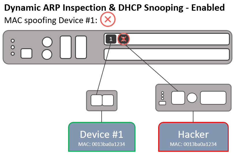
Dynamic ARP Inspection (DAI) is a security feature in ReadyLinks switches that protects networks against man-in-the-middle ARP spoofing attacks. DAI inspects Address Resolution Protocol (ARP) packets on the LAN and uses the information in the DHCP snooping table on the switch to validate ARP packets. DAI performs validation by intercepting each ARP packet and comparing its MAC and IP address information against the MAC-IP bindings contained in the DHCP snooping table. Any ARP packets that are inconsistent with the information contained in the DHCP snooping table are dropped.
GL-24xT-P600D# configure terminal
GL-24xT-P600D(config)# vlan 1
GL-24xT-P600D(vlan1)# arp-inspection#ARP inspection status and statistics
After you enable Dynamic ARP Inspection on a VLAN, use show arp-inspection status to see which VLANs have inspection enabled and which ports are trusted. Use show arp-inspection statistic to see how many ARP packets were forwarded or dropped per VLAN, and why. A rising DHCP Drops count usually means a device has a static IP with no matching DHCP snooping entry; add it with IP-MAC binding or move it to a trusted port.
- Restrict-forward limits where valid ARP traffic can go. Legitimate ARP requests are forwarded only out of trusted ports. ARP replies are forwarded based on the destination MAC address, or out of trusted ports if that MAC address is unknown. This keeps client-to-client ARP chatter off subscriber ports.
GL-24xT-P600D# configure terminal
GL-24xT-P600D(config)# vlan 1
GL-24xT-P600D(vlan1)# arp-inspection restrict-forward
Enable ARP Restrict Forwarding in this vlan successful!
GL-24xT-P600D(vlan1)# end
GL-24xT-P600D# show arp-inspection status
Dynamic ARP Inspection VLAN Status List
---------------------------------------
VID       Status       Restrict-forward
1         Enabled      Enabled

Dynamic ARP Inspection Port List
--------------------------------
PORT                Status
Ghn1        Untrust
Ghn2        Untrust
...
Fiber G1        Trust
GL-24xT-P600D# show arp-inspection statistic
Statistic Vlan's ARP Inspection Information
-------------------------------------------
VID                      1
Forwarded                1
Dropped                  34
DHCP Permits             0
DHCP Drops              34
Source MAC Failures       0
Dest MAC Failures         0
IP Validation Failures 0#ARP protective down recover
ARP protective down recover monitors the ARP traffic across ports with an ARP rate limit set and automatically re-enables ports that have been auto-disabled by the ARP rate limit.
ARP protective down recover is used in conjunction with ARP rate limits set on individual ports. Set the down recover interval to dictate how long the port will stay disabled until it is automatically enabled.
GL-4xTH-RPF# configure terminal
GL-4xTH-RPF(config)# arp protective-down recover
ARP recover has been configed successfully.
GL-4xTH-RPF(config)# arp protective-down recover interval
 interval                - 10-86400 sec
GL-4xTH-RPF(config)# arp protective-down recover interval 10
ARP recover interval has been configed successfully.
GL-4xTH-RPF(config)# exit
GL-4xTH-RPF# show arp rate-limit
ARP recover: enabled.
ARP recover interval : 10 s

PORT               RATE LIMIT STATE    RATE(pps)    Counter(pps)
--------------------------------------------------------------------------
Ghn1                    enabled           15            0
Ghn2                    enabled           15            0
Ghn3                    enabled           15            0
Ghn4                    enabled           15            0
Fiber G1               disabled           15            0
Fiber G2               disabled           15            0
MGMT disabled 15 0#Loop detection
Loop detection helps prevent network downtime in the event a loop occurs. This feature is disabled by default in ReadyLinks switches. It sends a loop-detection control packet and monitors those packets to detect the loop and shut down any affected ports. Each switch with loop detection enabled will periodically generate broadcast probe packets that are sent out on every active port. The default period is 30 seconds. Each port with loop detection enabled can be set to detect loops and automatically shut down the port in the event a loop occurs.
- Loop detection: A global device setting that enables loop detection on the switch.
- Loop detection interval: A global device setting that dictates the interval at which the broadcast probe packets are generated.
- Loop detection admin: A port setting that enables loop detection on a port. This setting must be enabled in conjunction with the Loop detection global setting.
- Loop detection control: A port setting that allows the port to shut down in the event a loop is detected. This setting must be enabled in conjunction with the Loop detection and Loop detection admin settings.
GL-24xT-P600D# configure terminal
GL-24xT-P600D(config)# loop-detection
GL-24xT-P600D(config)# interface ethernet RJ45/G1
GL-24xT-P600D(RJ45/G1)# loop-detection
GL-24xT-P600D(RJ45/G1)# loop-detection control#DHCP server
The ReadyLinks GL-x series switches have a built-in DHCP service. When enabled, it can provide DHCP to a configured subnet on a specified VLAN.
- VLAN: Specify the VLAN this DHCP server will reside on.
- Start IP: The first IP address of the range to be handed to clients.
- End IP: The last IP address of the range to be handed to clients.
- Subnet Mask: The subnet mask to hand to clients.
- Gateway: The default gateway IP address that should be given to clients on the subnet. This address must be in the same subnet as the clients.
- Lease time: How long (in minutes) clients will have an address allocated to them. Before the lease expires, the client must renew.
GL-24xT-P600D# configure terminal
GL-24xT-P600D(config)# ip dhcp server
 dns                       - configure DHCP Server DNS
 lease                     - configure DHCP Server lease time
 start-ip                  - configure a start IP address of DHCP Server
 vlan                      - VLAN ID(1-4094)
<cr>#DHCP server configuration
The built-in DHCP server is useful for small sites, provisioning benches, or isolated networks such as a camera VLAN that has no upstream DHCP server. Configure the address pool (start IP, end IP, subnet mask, and gateway), the DNS server, and the lease time, then enable the server. Use show ip dhcp-server to confirm the settings.
GL-24xT-P600D# configure terminal
GL-24xT-P600D(config)# ip dhcp-server start-ip 192.168.0.11 end-ip 192.168.0.21 netmask 255.255.255.0 gateway 192.168.0.1
GL-24xT-P600D(config)# ip dhcp-server dns 192.168.0.10
Configuration was successful.
GL-24xT-P600D(config)# ip dhcp-server lease-time 2
 Configuration was successful.
GL-24xT-P600D(config)# ip dhcp-server
 Enable DHCP server sucessfully
GL-24xT-P600D(config)# end
GL-24xT-P600D# show ip dhcp-server
 DHCP server : Enabled
 Start IP address : 192.168.0.11
 End IP address   : 192.168.0.21
 Subnet mask      : 255.255.255.0
 Gateway          : 192.168.0.1
 DNS              : 192.168.0.10
Lease time : 2#Multicast settings
IP multicast is a method of sending Internet Protocol (IP) datagrams to a group of interested receivers in a single transmission. It is often employed for streaming media applications on the Internet and private networks. Since traffic is sent from the source once in total, instead of once per recipient, throughput can be saved. Each host (and in fact each application on the host) that wants to be a receiving member of a multicast group (i.e. receive data corresponding to a particular multicast address) must use the Internet Group Management Protocol (IGMP) to join.
IGMP snooping is the process of listening to IGMP network traffic. The feature allows a network switch to listen in on the IGMP conversation between hosts and routers. By listening to these conversations, the switch maintains a map of which links need which IP multicast streams. Multicasts are filtered from the links which do not need them, which controls which ports receive specific multicast traffic.
- IGMP Snooping: Enable IGMP snooping to prevent the switch from sending multicast traffic to hosts that have not joined the multicast group.
- Fast leave: Allows the device to immediately remove a port from the forwarding entry for a multicast group when the port receives a leave message.
- Host timeout: The host timeout (seconds) value determines how long a switch waits to receive an IGMP query from a multicast router before removing a multicast group from its multicast cache table.
- Leave wait: Set the wait time before stopping traffic to a port when a leave message is received.
- Max response time: When a host receives a query packet, it starts counting to a random value less than the maximum response time. When this timer expires, the host replies with a report, provided that no other host has responded yet.
- Route timeout: The aging time (seconds) of the multicast router ports.
- IGMP Querier: Enable the built-in IGMP querier on the switch.
- Query transmit interval: How long (seconds) a query from the IGMP querier will be transmitted onto the network. Must be used in conjunction with the IGMP Querier.
GL-24xT-P600D# configure terminal
GL-24xT-P600D(config)# ip igmp snooping
 host-aging-time           - set host aging time
 immediate-leave           - enable immediate-leave of igmp snooping
 leave-wait                - set leave wait
 max-response-time         - set max response time
 querier                   - enable IGMP querier
 query-interval            - set query transmit interval
router-aging-time - set IGMP Snooing router aging time#IGMP snooping configuration
This section adds verification commands and per-VLAN settings to the Multicast settings above. IGMP snooping is enabled globally and then per VLAN, where you choose the IGMP version (v2 or v3). Every multicast VLAN needs an IGMP querier, either your multicast router or the switch's built-in querier. Without one, group memberships age out and streams stop after a few minutes.
- Fast leave: Removes a port from a group as soon as a leave message is received, which speeds up IPTV channel changes. Use it only on ports with a single receiver behind them.
- Static router port: Statically designates the port that leads to the multicast source or router, so streams are always forwarded toward it.
- Timers: Host aging time 200-1000s (default 260), router aging time 1-1000s (default 105), max response time 1-25s (default 10), and querier query interval 1-300s (default 125).
GL-24xT-P600D# configure terminal
GL-24xT-P600D(config)# ip igmp-snooping
ip igmp-snooping has been enabled.
GL-24xT-P600D(config)# ip igmp-snooping fast-leave
Fast-leave of ip igmp-snooping has been enabled.
GL-24xT-P600D(config)# ip igmp-snooping querier
IGMP querier has been enabled.
GL-24xT-P600D(config)# ip igmp-snooping query-interval 30
Query-interval of ip igmp-snooping has been set to 30 seconds
GL-24xT-P600D(config)# ip igmp-snooping host-aging-time 300
Host-aging-time of ip igmp-snooping set to 300 seconds

GL-24xT-P600D(config)# vlan 1
GL-24xT-P600D(vlan1)# ip igmp-snooping version v3
ip igmp-snooping has been enabled on vlan 1.
GL-24xT-P600D(vlan1)# multicast static-router-port ethernet Fiber/G1
Set port successfully.
GL-24xT-P600D(vlan1)# end

GL-24xT-P600D# show ip igmp-snooping configuration
ip igmp-snooping global state          :Enabled
Host Timeout                      :300
Route Timeout                     :105
IGMP Querier                      :Enabled
Query Transmit Interval           :30
Max Response Time                 :10
Fast Leave                        :Enabled
GL-24xT-P600D# show ip igmp-snooping group
show ip igmp-snooping group information
Vlan ID:           1
Multicast group:   239.0.0.10
MAC address:       01-00-5e-00-00-0a
Port Member:       0/4,
Total Entries: 1#Static multicast entries and unknown multicast flood
You can add static multicast MAC entries so a group is always forwarded to specific ports, regardless of IGMP. This is useful for receivers that don't send IGMP joins, such as some digital signage players and legacy encoders.
By default, each VLAN floods unknown multicast (groups with no IGMP membership) to all ports. Disabling unknown-multicast-flood on a VLAN keeps unwanted streams off subscriber ports, but make sure IGMP snooping and a querier are working first. Otherwise, legitimate multicast that hasn't been learned will be dropped.
GL-24xT-P600D# configure terminal
GL-24xT-P600D(config)# mac-address multicast 01-00-5e-00-00-e8 interface ethernet Ghn1 to ethernet Ghn2 vlan 2
The configuration succeeds.
GL-24xT-P600D(config)# vlan 5
GL-24xT-P600D(vlan5)# no unknown-multicast-flood
GL-24xT-P600D(vlan5)# end
GL-24xT-P600D# show mac-address multicast
GL-24xT-P600D# show vlan unknown-multicast-flood
VLAN ID: 1 Unknown Multicast Flood: Enabled
VLAN ID: 5 Unknown Multicast Flood: Disabled#Multicast VLAN registration (MVR)
MVR delivers a single multicast VLAN, such as an IPTV channel lineup, to subscribers who are in different VLANs. The stream enters the switch once on the multicast VLAN through the source port and is replicated only to receiver ports that have joined a group. Subscribers stay isolated in their own VLANs, and the uplink carries only one copy of each stream.
Set the multicast VLAN (2-4094), add the multicast group addresses, and assign port roles: source for the uplink toward the headend and receiver for subscriber ports. In dynamic mode (default), IGMP reports from receivers are forwarded to the source ports, so streams are only pulled when needed. Compatible mode forwards all MVR groups to the source ports and doesn't forward IGMP reports upstream.
GL-24xT-P600D# configure terminal
GL-24xT-P600D(config)# ip igmp-snooping
GL-24xT-P600D(config)# mvr
MVR has been enabled.
GL-24xT-P600D(config)# mvr mVlanId 200
multicast vlan id of mvr set to 200
GL-24xT-P600D(config)# mvr group 225.1.1.2
GL-24xT-P600D(config)# mvr mode dynamic
GL-24xT-P600D(config)# mvr port type source ethernet Fiber/G1
Configuration completed successfully.
GL-24xT-P600D(config)# mvr port type receiver ethernet Ghn1 to ethernet Ghn24
Configuration completed successfully.
GL-24xT-P600D(config)# end
GL-24xT-P600D# show mvr configuration
MVR Global state         : Enabled
Multicast Vlan Id        : 200
Mode                     : dynamic
GL-24xT-P600D# show mvr port
source ports:
Fiber/G1
receiver ports:
Ghn1 Ghn2 Ghn3 ...#TACACS+
TACACS (Terminal Access Controller Access Control System) is a security protocol that provides centralized validation of users who are attempting to gain access to a ReadyLinks device. TACACS+ provides separate authentication, authorization and accounting services.
Adding a TACACS+ server:
- IP Address: Enter the IP address of your TACACS+ server.
- TCP Port ID: TACACS+ server port ID.
- Key: TACACS+ key.
GL-24xT-P600D# configure terminal
GL-24xT-P600D(config)# tacacs-server host {ip_address} port {port_id} key {key}#TACACS+ verification and login authentication
Adding a TACACS+ server doesn't change how users log in until you point a login method at it. The aaa authentication login command sets, separately for console, telnet, ssh, and http (web) access, whether logins are checked against local accounts or the tacacs server. show aaa displays the current method for each, and show tacacs-server confirms the server address, port (default 49), and key.
GL-24xT-P600D# configure terminal
GL-24xT-P600D(config)# tacacs-server host 192.168.105.249 port 49 key aa
The configuration of TACACS+ server has been completed successfully.
GL-24xT-P600D(config)# aaa authentication login ssh tacacs
The configuration has been completed successfully.
GL-24xT-P600D(config)# aaa authentication login telnet tacacs
The configuration has been completed successfully.
GL-24xT-P600D(config)# aaa authentication login console local
The configuration has been completed successfully.
GL-24xT-P600D(config)# end
GL-24xT-P600D# show tacacs-server
TACACS+ server information
Server    :  192.168.105.249
Port      :  49
Key       :  aa
GL-24xT-P600D# show aaa
console : local
telnet  : tacacs
ssh     : tacacs
http : local#Auto reboot
Auto reboot is a useful function when troubleshooting a network, but is not recommended for continued use in production networks. When enabled, this feature causes the device to automatically reboot if it is unable to ping its gateway. A ping to the gateway is sent every 10 seconds when this feature is enabled.
Enabling auto reboot:
- ping-not-respond-count: The number of pings that must fail before the device auto-reboots.
- reset-count: The number of times the device will reboot.
GL-24xT-P600D# configure terminal
GL-24xT-P600D(config)# auto-reset
 disable                   - disable auto-reset function
 enable                    - enable auto-reset function
 ping-not-respond-count    - set auto-reset ping not respond times
 reset-count               - set auto-reset times
GL-24xT-P600D(config)# auto-reset enable
Set Auto Reset Function Enable successfully.
GL-24xT-P600D(config)# end
GL-24xT-P600D# show auto-reset
Auto Reset Configuration is:
        Auto-Reset:Enable
        Auto-Reset State:Running
        Auto-Reset Reset Count:5
Auto-Reset Ping Count:5#Virtual interface settings
#Management interface
By default, ReadyLinks switches come with one virtual interface on VLAN 1 set as a DHCP client. The devices connect back to the ReadyView dashboard on the default untagged VLAN 1. You can change the management VLAN and uplink port setting (tagged/untagged) once the device is online and adopted into your dashboard.
If your network does not allow default VLAN 1 to connect to the Internet, you will need to manually assign the management VLAN. Set up the device on a provisioning network with DHCP and apply a template that adjusts the management VLAN and uplink type.
GL-24xT-P600D# configure terminal
GL-24xT-P600D(config)# interface vlan 1
GL-24xT-P600D(vlan-interface1)#
 end                       - exit from current environment
 exit                      - exit to root prompt
 ip                        - IP
 ipv6                      - IPv6
no - disable a protocol/funtion, or restore port default configuration#Management IP address
Within a VLAN interface, ip address sets how the switch gets its management address: dhcp for a DHCP client, or a static IP address, netmask, and gateway. You can also add a secondary IP address with the sub keyword, for example to keep a provisioning-subnet address while you migrate, and an IPv6 address with ipv6 address.
show vlan interface lists each VLAN interface with its addressing. show management displays the active Management mode. Change addressing from a console session, or make sure the new address is reachable before you apply it, so you don't lose access to the switch.
GL-24xT-P600D# configure terminal
GL-24xT-P600D(config)# interface vlan 1
GL-24xT-P600D(vlan-interface1)# ip address 10.1.1.11 255.255.255.0 10.1.1.1
The configuration is successful.
GL-24xT-P600D(vlan-interface1)# ip address 192.168.10.12 255.255.255.0 sub
The configuration is successful
GL-24xT-P600D(vlan-interface1)# ipv6 address 2001:1:1:1::1/64
The configuration successfully.
GL-24xT-P600D(vlan-interface1)# end
GL-24xT-P600D# show vlan interface

VLAN INTERFACE   TYPE    IPv4 ADDRESS/NETMASK/GATEWAY     SECONDARY IP        IPv6
--------------------------------------------------------------------
VLAN-INTERFACE1  Manual  10.1.1.11/255.255.255.0/10.1.1.1    192.168.10.12/255.255.255.0/0.0.0.0    2001:1:1:1::1/64
GL-24xT-P600D# show management
Management mode is disabled.#IP routing
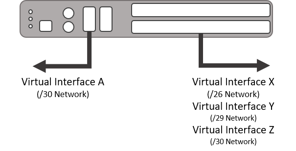
IP routing is enabled by default when you create a new virtual interface. This means you can use your virtual interfaces to set up IP routes on your device.
#VLANs
#VLAN mode
ReadyLinks switches support two VLAN modes, and only one can be active at a time:
- 802.1Q (
8021Q): Standards-based tagged VLANs (IDs 1-4094) that can span multiple switches. This is the mode used by ReadyView, and it's what most deployments need. See 802.1Q VLANs. - Port-based (
port-based): Simple groups of ports that can only communicate with each other on this switch, with no tagging. See Port-based VLANs.
Changing the VLAN mode changes how every port forwards traffic and can cut off management access. Make the change from the console or during a maintenance window.
GL-24xT-P600D# show vlan-mode
Current vlan mode is 802.1Q vlan.
GL-24xT-P600D# configure terminal
GL-24xT-P600D(config)# vlan-mode 8021Q#802.1Q VLANs
802.1Q VLANs split one physical switch into separate broadcast domains, for example one VLAN per subscriber, a camera VLAN, and a management VLAN. The VLAN ID travels with each frame as a tag, so the same VLANs can be carried across uplinks to other switches and routers. For background on tagging and PVIDs, see VLAN and port settings.
Create a VLAN with vlan <id>. From the VLAN view, you can name the VLAN (no spaces) and add ports as tagged (frames keep their VLAN tag, typical for uplinks and trunks) or untagged (the tag is removed, typical for end devices). Port ranges use to ethernet. Use switchport forbidden to keep a port out of the VLAN. to vlan <id> creates a consecutive range of VLANs. Remove VLANs with no vlan <id>, no vlan <id> to <id>, or no vlan all.
GL-24xT-P600D# configure terminal
GL-24xT-P600D(config)# vlan 10
GL-24xT-P600D(vlan10)# name Cameras
set vlan group description successfully!!!
GL-24xT-P600D(vlan10)# switchport tagged ethernet Fiber/G1
GL-24xT-P600D(vlan10)# switchport untagged ethernet Ghn1 to ethernet Ghn8
GL-24xT-P600D(vlan10)# end
GL-24xT-P600D# show vlan 10
  VLAN ID: 10
  VLAN Type:  static
  Description: Cameras
  Tag Ports:
  Fiber/G1
  unTag Ports:
  Ghn1         Ghn2         Ghn3 ...
  Forbidden Ports:
GL-24xT-P600D# configure terminal
GL-24xT-P600D(config)# no vlan 20 to 30#Port VLAN settings
Each port also has VLAN settings that control how it handles tagged and untagged frames:
- Link type:
access(one untagged VLAN, for end devices),trunk(multiple tagged VLANs, for uplinks), orhybrid(a mix of tagged and untagged VLANs, the default).switchport link-type trunk permit vlan alladds a trunk port as tagged to every VLAN that already exists, except VLANs where the port is already untagged. VLANs created later must be added separately. - PVID: The VLAN that untagged incoming frames are placed in (default VLAN 1). On an access port, set the PVID to the same VLAN the port is an untagged member of.
- Admit frame:
all(default) oronly-tag, which drops untagged frames. This is useful on trunks. - Ingress filtering: Drops incoming frames tagged with a VLAN the port isn't a member of.
show interface switchport ethernet <port> shows a port's VLAN membership, PVID, link type, and frame settings.
GL-24xT-P600D# configure terminal
GL-24xT-P600D(config)# interface ethernet Ghn1
GL-24xT-P600D(Ghn1)# switchport pvid 10
Settings are updated successfully!

GL-24xT-P600D(config)# interface ethernet Fiber/G1
GL-24xT-P600D(Fiber/G1)# switchport link-type trunk
Settings are updated successfully!
GL-24xT-P600D(Fiber/G1)# switchport link-type trunk permit vlan all
Configuration successfully.
GL-24xT-P600D(Fiber/G1)# switchport admit-frame only-tag
Settings are updated successfully!
GL-24xT-P600D(Fiber/G1)# switchport ingress-filtering
Ingress-filtering has been enabled successfully!
GL-24xT-P600D(Fiber/G1)# end
GL-24xT-P600D# show interface switchport ethernet Ghn1
 Vlan vid: 10
 Egress rule: untagged
 Port membership type: static
 Pvid: 10
 Link type: Hybrid
 Frame type: Admit all
Ingress filter: Disabled#Port-based VLANs
Port-based VLANs are a simple way to segment ports on a single switch without tags. Each port-based VLAN (ID 1-255) is a group of ports that can only exchange traffic with each other. Because there are no tags, these VLANs can't be extended to other switches. If you need that, use 802.1Q VLANs. To isolate individual subscriber ports from each other, see Port isolation.
Port-based VLANs require the VLAN mode to be set to port-based.
GL-24xT-P600D# configure terminal
GL-24xT-P600D(config)# vlan-mode port-based
Config port based vlan successfully!
GL-24xT-P600D(config)# port-based-vlan 3
GL-24xT-P600D(port-based-vlan-3)# description Building-A
GL-24xT-P600D(port-based-vlan-3)# interface ethernet Ghn1 to ethernet Ghn4
Add the port successfully.
GL-24xT-P600D(port-based-vlan-3)# end
GL-24xT-P600D# show port-based-vlan all#VLAN-VPN (QinQ)
VLAN-VPN, also known as QinQ or double tagging, adds an outer "service" VLAN tag on top of a customer's existing tag. Service providers use it to carry many customer VLANs across a shared backbone in a single service VLAN, without the customer and provider VLAN numbers conflicting.
Enable VLAN-VPN globally and on the participating ports, optionally set the outer tag's TPID (default 0x8100), then define QinQ rules per port. Each rule specifies the incoming VLAN (or range), the outer VLAN ID to add, and the outer tag's 802.1p priority (0-7). Use newInnerVid to also rewrite the inner VLAN ID. Double tagging adds 4 bytes to each frame, so check MTU along the path (see Port configuration).
GL-24xT-P600D# configure terminal
GL-24xT-P600D(config)# vlan-vpn
Vlan-vpn has been enabled successfully.
GL-24xT-P600D(config)# interface ethernet Ghn1
GL-24xT-P600D(Ghn1)# vlan-vpn
GL-24xT-P600D(Ghn1)# vlan-vpn QinQ priority 5 new-vid 100 old-vid 200 to 300
QinQ has been configured successfully.
GL-24xT-P600D(Ghn1)# end
GL-24xT-P600D# show vlan-vpn#VLAN mapping
VLAN mapping (VLAN translation) rewrites VLAN tags on a port, so a customer's VLAN can be carried on a different service VLAN pair in the provider network. Each mapping has three VLAN IDs: the service outer VID (the network's outer tag), the service inner VID (the private service network tag), and the customer inner VID (the customer network tag).
Mappings are configured per port. To remove a mapping, use the no vlan-translation form with the same three VLAN IDs. View mappings with show vlan-translation.
GL-24xT-P600D# configure terminal
GL-24xT-P600D(config)# interface ethernet Ghn1
GL-24xT-P600D(Ghn1)# vlan-mapping service-outer-vid 1000 service-inner-vid 501 customer-inner-vid 505
Configure the VLAN translation successfully
GL-24xT-P600D(Ghn1)# no vlan-translation service-outer-vid 1000 service-inner-vid 501 customer-inner-vid 505
Clear the VLAN translation successfully
GL-24xT-P600D(Ghn1)# end
GL-24xT-P600D# show vlan-translation#Layer 2 switching
#Spanning tree
Spanning Tree Protocol prevents layer 2 loops when switches are connected with redundant links. It blocks the redundant paths and reopens them automatically if the active path fails. Spanning tree is disabled by default. Loop detection protects against accidental loops on edge ports, while spanning tree is the standards-based choice when you intentionally build redundant links between switches.
ReadyLinks switches support STP, RSTP (rapid, recommended for most networks), and MSTP (see Multiple spanning tree (MSTP)). Spanning tree can be enabled globally and per port. Key settings:
- Bridge priority: The switch with the lowest priority becomes the root bridge. The range is 0-65535 and the default is 32768. Set a lower value on your core or aggregation switch so the root is placed deliberately rather than by lowest MAC address.
- Edge port: Mark ports that connect to end devices as edge ports so they move to forwarding immediately. An edge port that receives a BPDU becomes a normal port again.
- BPDU guard: A global setting that protects edge ports from receiving BPDUs, for example from a rogue switch plugged into a subscriber port.
- Root guard: A port setting that prevents a downstream switch from becoming the root bridge.
- Path cost / port priority: Influence which redundant link is chosen as forwarding. Port priority ranges from 0-255 (default 128). Path cost defaults to auto.
- Timers: Hello time (default 2s), max age (default 20s), and forward delay (default 15s) are set on the root bridge. They must satisfy
2 x (forward delay - 1) >= max ageandmax age >= 2 x (hello time + 1).
GL-24xT-P600D# configure terminal
GL-24xT-P600D(config)# spanning-tree
GL-24xT-P600D(config)# spanning-tree mode rstp
Set successfully
GL-24xT-P600D(config)# spanning-tree priority 4096
Configure stp successfully!
GL-24xT-P600D(config)# spanning-tree bpdu-guard
Set successfully!

GL-24xT-P600D(config)# interface ethernet Ghn1
GL-24xT-P600D(Ghn1)# spanning-tree edge
Set successfully

GL-24xT-P600D(config)# interface ethernet Fiber/G2
GL-24xT-P600D(Fiber/G2)# spanning-tree root-guard
Set successfully!
GL-24xT-P600D(Fiber/G2)# spanning-tree path-cost 300
Set successfully!
GL-24xT-P600D(Fiber/G2)# end

GL-24xT-P600D# show spanning-tree

     The spanning tree is enabled on this switch!

  The spanning tree mode is RSTP!

    Bridge Priority:4096
    Hello time:2
    Max age time:20
    Forward delay time:15
    BPDU guard: Enabled
...#Multiple spanning tree (MSTP)
MSTP maps groups of VLANs to separate spanning tree instances. Each instance can use a different root bridge and forwarding path, so redundant uplinks can carry traffic at the same time (for example, VLANs 10-20 on one uplink and VLANs 30-40 on the other) instead of leaving one link idle.
Switches belong to the same MST region only if their region name, revision level, and VLAN-to-instance mapping match exactly, so configure all three the same on every switch in the region. Set the spanning tree mode to mstp first.
GL-24xT-P600D# configure terminal
GL-24xT-P600D(config)# spanning-tree mode mstp
GL-24xT-P600D(config)# spanning-tree mst-region
GL-24xT-P600D(mst-region)# region-name example
configure mstp region name successfully!
GL-24xT-P600D(mst-region)# revision-level 25
configure mstp region level successfully!
GL-24xT-P600D(mst-region)# instance 3
Enable this msti successfully.
GL-24xT-P600D(mst-region)# instance 3 vlan 4 to 6
Set successfully
GL-24xT-P600D(mst-region)# instance 3 priority 4096
Set successfully
GL-24xT-P600D(mst-region)# end
GL-24xT-P600D# show spanning-tree mst-configuration#MAC address table
The MAC address table maps each learned MAC address to a port and VLAN, so the switch knows where to forward frames. Use it to find which port a device is connected to, or to confirm that a G.hn endpoint and the client behind it have been learned.
Dynamic entries age out after 300 seconds by default (range 10-1000000 seconds). If the aging time is too short, the switch floods traffic for MAC addresses that are still active. If it's too long, the table is slow to reflect devices that have moved. You can also add static entries that never age out, or blackhole entries that drop all traffic to a MAC address.
GL-24xT-P600D# show mac-address-table
show the mac address table
MAC ADDRESS          VLAN ID       STATE        PORT           AGING
6c-f0-49-8a-1d-e3    1             Dynamic      RJ45/G1        Yes
6c-f0-49-81-5c-07    1             Learned      RJ45/G1        Yes
00-1e-6e-dd-63-67    1             Static       CPU            No
GL-24xT-P600D# show mac-address interface ethernet Ghn1
GL-24xT-P600D# show mac-address vlan 10 count
GL-24xT-P600D# show mac-address aging-time
The aging time of mac address is 300s.
GL-24xT-P600D# configure terminal
GL-24xT-P600D(config)# mac-address static 001d.7223.ed70 interface ethernet Ghn1 vlan 3
GL-24xT-P600D(config)# mac-address timer aging 500
Aging time of dynamic MAC address is 500 seconds.
GL-24xT-P600D(config)# no mac-address vlan 3
Delete mac address successfully.#Storm control
Storm control limits how much broadcast, multicast, and unknown unicast (DLF, destination lookup failed) traffic a port will accept. When the limit is exceeded, the excess packets are dropped, so a looped cable or a misbehaving client cannot saturate every port in the VLAN. Storm control is disabled by default and can be set globally or per port.
Limits are set in packets per second (1-262143). Choose the traffic types to limit with a type number:
| Type | Traffic limited |
|---|---|
| 1 | Broadcast |
| 2 | Multicast |
| 3 | Unknown unicast (DLF) |
| 4 | Broadcast + Multicast |
| 5 | Broadcast + DLF |
| 6 | Multicast + DLF |
| 7 | Broadcast + Multicast + DLF |
GL-24xT-P600D# configure terminal
GL-24xT-P600D(config)# storm-control type 1 level pps 64
Configuration completed successfully

GL-24xT-P600D(config)# interface ethernet Ghn1
GL-24xT-P600D(Ghn1)# storm-control type 5 level pps 222
Configuration completed successfully
GL-24xT-P600D(Ghn1)# end
GL-24xT-P600D# show storm-control#Port mirroring
Port mirroring copies the traffic from one or more source ports to a monitor port, where you can capture it with a protocol analyzer such as Wireshark. It's one of the most useful tools for troubleshooting DHCP, multicast, or VoIP problems on a specific subscriber port.
Up to four mirror groups are supported. In each group, set the monitor port (destination) first, then add mirroring ports (sources) and choose the direction: ingress (received), egress (sent), or both. If the mirrored traffic exceeds the monitor port's speed, some of it will be dropped. Remove mirror groups when you're done troubleshooting.
GL-24xT-P600D# configure terminal
GL-24xT-P600D(config)# mirror group 1
GL-24xT-P600D(MIRROR-1)# monitor-port ethernet RJ45/G2
Configuration completed successfully.
GL-24xT-P600D(MIRROR-1)# mirroring-port ethernet Ghn1 to ethernet Ghn4 both
Configuration completed successfully.
GL-24xT-P600D(MIRROR-1)# end
GL-24xT-P600D# show mirror
GL-24xT-P600D# configure terminal
GL-24xT-P600D(config)# mirror group 1
GL-24xT-P600D(MIRROR-1)# no mirroring-port
Configuration completed successfully.#LLDP
Link Layer Discovery Protocol (LLDP) lets the switch advertise its identity and learn about directly connected neighbors, such as their system name, port, capabilities, and management IP address. It's useful for documenting and verifying cabling, especially on uplinks to other switches, routers, and access points.
LLDP is disabled globally by default. After you enable it globally, set each port's admin status to rxtx (send and receive), tx, rx, or disable. Timers control how often LLDP frames are sent (tx-interval, default 30s) and how long neighbors keep the information (tx-hold multiplier, default 4). lldp tlv-enable basic-tlv selects which optional fields are advertised.
GL-24xT-P600D# configure terminal
GL-24xT-P600D(config)# lldp
Settings are updated successfully!
GL-24xT-P600D(config)# lldp timer tx-interval 30
Settings are updated successfully!
GL-24xT-P600D(config)# lldp tlv-enable basic-tlv all
Settings are updated successfully!

GL-24xT-P600D(config)# interface ethernet Fiber/G1
GL-24xT-P600D(Fiber/G1)# lldp admin-status rxtx
Settings are updated successfully!
GL-24xT-P600D(Fiber/G1)# end
GL-24xT-P600D# show lldp neighbor-information
Local Port               : Fiber/G1
Chassis ID               : 00-1e-6e-dd-63-67(mac address)
Remote Port ID           : 16(local)
System Name              : -
Port description         : Ghn1
System Capabilities      : Bridge(+)
Management Address       : 172.16.0.16
GL-24xT-P600D# show lldp status
GL-24xT-P600D# show lldp statistics#Link aggregation
Link aggregation bundles several physical ports into one logical link for more bandwidth and redundancy. If a member link fails, traffic continues on the remaining members. It's typically used on uplinks to a core switch or router. Up to 16 aggregation groups are supported.
Create the group globally with mode manual (ports are bundled without negotiation) or static. Then add member ports from each port's view. To negotiate the bundle with the far end using LACP, enable lacp globally and on each member port, and set each port's LACP mode to active (initiates negotiation) or passive (responds only). At least one end must be active. lacp system-priority and lacp port-priority (1-65535) influence which side and which ports take priority.
GL-24xT-P600D# configure terminal
GL-24xT-P600D(config)# link-aggregation group 1 mode static
The link-aggregation group is in the Static Mode now.
The configuration is successful.
GL-24xT-P600D(config)# link-aggregation group 1 description Uplink-Core
The configuration is successful.
GL-24xT-P600D(config)# lacp
LACP is enabled now!

GL-24xT-P600D(config)# interface ethernet Fiber/G1
GL-24xT-P600D(Fiber/G1)# link-aggregation group 1
The port is added into the link-aggregation group.
GL-24xT-P600D(Fiber/G1)# lacp
The port is enabled!
GL-24xT-P600D(Fiber/G1)# lacp mode active
GL-24xT-P600D(Fiber/G1)# lacp port-priority 50
The port priority is 50 now.
GL-24xT-P600D(Fiber/G1)# end
GL-24xT-P600D# show link-aggregation summary
GL-24xT-P600D# show link-aggregation verbose 1
GL-24xT-P600D# show lacp mode#Access security
#802.1X port authentication
802.1X requires a device to authenticate against a RADIUS server before its port is allowed to pass traffic. Use it on ports where unknown users could plug in, such as common areas, conference rooms, and staff jacks. Until a device authenticates, only EAPoL authentication traffic is allowed on the port.
Configure 802.1X in the dot1x view: enable it with system-auth-control, then set the RADIUS authentication server (default port 1812) and shared key (1-15 characters). A RADIUS accounting server (default port 1813) is configured with radius-server accounting. Optional settings include a guest VLAN for devices that fail or don't support 802.1X, the maximum number of request retries (max-req, 1-10), and timers such as reauth-period (60-7200s, default 3600) and quiet-period (default 60s).
On each port, enable dot1x and set the port control mode:
- auto: Clients must authenticate (normal operation).
- forceauthorized: The port is always open with no authentication.
- forceunauthorized: The port is always blocked.
GL-24xT-P600D# configure terminal
GL-24xT-P600D(config)# dot1x
GL-24xT-P600D(dot1x)# system-auth-control
802.1x has been enabled
Configuration completed successfully.
GL-24xT-P600D(dot1x)# radius-server authentication host 192.168.0.234 auth-port 1812 key secret
Configuration completed successfully.
GL-24xT-P600D(dot1x)# guest-vlan 99
Guest Vlan has been set.
GL-24xT-P600D(dot1x)# max-req 5
Max request count has been set 5.
GL-24xT-P600D(dot1x)# timeout quiet-period 120
Timeout of the quiet period is 120 seconds.
GL-24xT-P600D(dot1x)# end

GL-24xT-P600D# configure terminal
GL-24xT-P600D(config)# interface ethernet Ghn5
GL-24xT-P600D(Ghn5)# dot1x
GL-24xT-P600D(Ghn5)# dot1x port-control auto
The configuration succeeds.
GL-24xT-P600D(Ghn5)# dot1x re-authentication
The configuration succeeds.
GL-24xT-P600D(Ghn5)# end
GL-24xT-P600D# show dot1x status
GL-24xT-P600D# show dot1x interface ethernet Ghn5
GL-24xT-P600D# show dot1x radius-server#MAC authentication
MAC authentication checks a device's MAC address against the RADIUS server the first time the switch sees it, without any client software or credentials. Use it for devices that can't run 802.1X, such as IP cameras, printers, and IoT sensors, when you want only known hardware on a port.
Enable MAC authentication globally, then on each port that should use it. It uses the RADIUS server configured in the 802.1X port authentication dot1x view. Timers control how often the switch checks whether a user has gone offline (offline-detect, default 300s), how long it waits before re-authenticating a device that failed (quiet, default 60s), and the RADIUS server-timeout (default 100s).
GL-24xT-P600D# configure terminal
GL-24xT-P600D(config)# mac-authentication
Configuration has been completed successfully!
GL-24xT-P600D(config)# mac-authentication timer quiet 120
Configuration has been completed successfully!
GL-24xT-P600D(config)# interface ethernet Ghn1
GL-24xT-P600D(Ghn1)# mac-authentication
Configuration has been completed successfully!
GL-24xT-P600D(Ghn1)# end
GL-24xT-P600D# show mac-authentication configuration
GL-24xT-P600D# show mac-authentication information#Access control lists
Access Control Lists (ACLs) permit or deny traffic that matches specific criteria. You can also rate-limit matching traffic or count it. ACLs are created globally and then applied to individual ports with packet-filter. The ACL number determines its type:
- Basic ACLs (1-20): Match on source IP address. Up to 15 rules per ACL.
- Advanced ACLs (21-40): Match on source and destination IP address and TCP/UDP ports. Up to 5 rules per ACL.
- L2 ACLs (41-60): Match on source and destination MAC address. Up to 15 rules per ACL.
Each rule has an ID, an action (permit or deny), and a match string. The match string format differs by ACL type, so build it interactively with ? after rule <id> permit advanced or rule <id> permit l2.
- Traffic limit: Applied to a permit rule. Rate-limits matching traffic to a target rate in kbps (64-1000000, in multiples of 64) with a burst size of 4-512 KB.
- Traffic statistics: Counts packets that match a rule. Results appear in
show acl number.
For broad protection against broadcast or multicast floods, use Storm control instead.
GL-24xT-P600D# configure terminal
GL-24xT-P600D(config)# acl number 10
GL-24xT-P600D(ACL-basic-10)# rule 2 deny basic source 192.168.0.1 255.255.255.0
Configuration has been completed successfully!
GL-24xT-P600D(ACL-basic-10)# rule 3 permit basic source 192.168.20.0 255.255.255.0
Configuration has been completed successfully!
GL-24xT-P600D(ACL-basic-10)# traffic-limit rule 3 target-rate 128 burst-bucket 8
Configuration has been completed successfully!
GL-24xT-P600D(ACL-basic-10)# traffic-statistic rule 3
Configuration has been completed successfully!
GL-24xT-P600D(ACL-basic-10)# end

GL-24xT-P600D# configure terminal
GL-24xT-P600D(config)# interface ethernet Fiber/G1
GL-24xT-P600D(Fiber/G1)# packet-filter acl-number 10
Configuration has been completed successfully!
GL-24xT-P600D(Fiber/G1)# end
GL-24xT-P600D# show acl number 10#IP source guard
IP Source Guard (ip-check-source) drops IP traffic on a port unless its source address matches a known binding. Bindings come from the DHCP snooping table or from static IP-MAC binding entries. This stops clients from spoofing another subscriber's IP address or assigning themselves a static address.
Enable it on subscriber-facing ports, not on uplinks. Devices with static IP addresses on a protected port need a static IP-MAC binding, or they'll lose connectivity.
GL-24xT-P600D# configure terminal
GL-24xT-P600D(config)# interface ethernet Ghn1
GL-24xT-P600D(Ghn1)# ip-check-source
IP source guard has been enabled on port Ghn1
GL-24xT-P600D(Ghn1)# end
GL-24xT-P600D# show ip-check-source status

PORT               IP CHECK SOURCE
--------------------------------------------------------------------------
Ghn1          enabled
Ghn2          disabled
...#IP-MAC binding
IP-MAC binding statically ties an IP address and MAC address to a specific port. Bindings are used by IP source guard and Dynamic ARP inspection to allow devices with static IP addresses, such as cameras, printers, and building controllers, on protected ports that would otherwise require a DHCP snooping entry.
Enter the ip-binding view to add or remove bindings. no user-bind ethernet <port> clears all bindings on a port, and no user-bind all clears every binding.
GL-24xT-P600D# configure terminal
GL-24xT-P600D(config)# ip ip-binding
GL-24xT-P600D(ip-binding)# user-bind mac-addr 0000.0000.0011 ip-addr 192.168.114.145 ethernet Ghn5
Configuration has been completed successfully.
GL-24xT-P600D(ip-binding)# end
GL-24xT-P600D# show ip-binding
ip-binding information:
       ip                 mac                interface
192.168.114.145 00-00-00-00-00-11 Ghn5#Port settings
#DHCP trust
With DHCP snooping enabled globally on the switch, you can set ports to trust or untrust DHCP packets that traverse those ports.
GL-24xT-P600D# configure terminal
GL-24xT-P600D(config)# ip dhcp snooping interface ethernet Fiber/G1 trust#DHCP rate limit
With DHCP rate limiting set on a port, the port will automatically disable when the DHCP packets per second exceed the rate limit that is set.
Use DHCP rate limiting in conjunction with DHCP protective down recover to automatically re-enable ports that are shut down due to rate limiting.
GL-4xTH-RPF# configure terminal
GL-4xTH-RPF(config)# interface ethernet Ghn1
GL-4xTH-RPF(Ghn1)# ip dhcp rate-limit rate 100
DHCP rate has been configed successfully.
GL-4xTH-RPF(config)# exit
GL-4xTH-RPF# show ip dhcp rate-limit
DHCP recover: enabled.
DHCP recover interval : 10 s

PORT               RATE LIMIT STATE    RATE(pps)    Counter(pps)
--------------------------------------------------------------------------
Ghn1                    enabled           100            0
Ghn2                    enabled           15            0
Ghn3                    enabled           15            0
Ghn4                    enabled           15            0
Fiber G1               disabled           15            0
Fiber G2               disabled           15            0
MGMT disabled 15 0#ARP trust
With Dynamic ARP inspection enabled on a VLAN, you can set ports to trust or untrust ARP packets that traverse those ports.
GL-24xT-P600D# configure terminal
GL-24xT-P600D(config)# interface ethernet Fiber/G1
GL-24xT-P600D(Fiber/G1)# arp-inspection trust#ARP rate limit
With ARP rate limiting enabled and a rate limit set on a port, the port will automatically disable when the ARP packets per second exceed the rate limit that is set.
Use ARP rate limiting in conjunction with ARP protective down recover to automatically re-enable ports that are shut down due to rate limiting.
GL-4xTH-RPF# configure terminal
GL-4xTH-RPF(config)# interface ethernet Ghn1
GL-4xTH-RPF(Ghn1)# arp rate-limit rate 100
ARP rate has been configed successfully.
GL-4xTH-RPF(config)# exit
GL-4xTH-RPF# show arp rate-limit
ARP recover: enabled.
ARP recover interval : 10 s

PORT               RATE LIMIT STATE    RATE(pps)    Counter(pps)
--------------------------------------------------------------------------
Ghn1                    enabled           100            0
Ghn2                    enabled           15            0
Ghn3                    enabled           15            0
Ghn4                    enabled           15            0
Fiber G1               disabled           15            0
Fiber G2               disabled           15            0
MGMT disabled 15 0#Port isolation
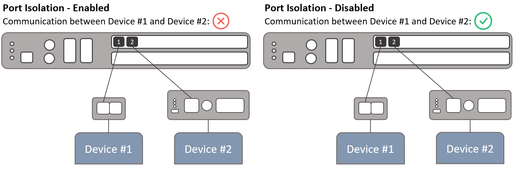
Port isolation provides layer 2 isolation between protected ports on a switch. By default, ReadyLinks switches do not isolate WAN-facing ports, but port isolation is enabled on ReadyLinks LAN ports.
GL-24xT-P600D# configure terminal
GL-24xT-P600D(config)# interface ethernet Fiber/G1
GL-24xT-P600D(Fiber/G1)# switchport protected#Throughput rate limits
Set rate limits on individual ports to impose a throughput ceiling on the port. Rate limits can be set asymmetrically, meaning the upload limit and the download limit do not need to match.
#Port rate limit configuration
This section shows the CLI for the Throughput rate limits setting above. line-rate sets a throughput ceiling on a port, separately for each direction:
- ingress: Traffic the switch receives on the port (upload, from the subscriber's point of view).
- egress: Traffic the switch sends out of the port (download, from the subscriber's point of view).
Valid rates are 64k, 128k, 192k, 256k, 320k, 484k, 512k, 640k, 768k, 896k, 1m, 2m, 4m, 8m, 10m, 15m, 20m, 30m through 100m in steps of 10, and 200m through 900m in steps of 100. Use no line-rate egress or no line-rate ingress to remove a limit.
GL-24xT-P600D# configure terminal
GL-24xT-P600D(config)# interface ethernet Ghn1
GL-24xT-P600D(Ghn1)# line-rate egress rate 100m
GL-24xT-P600D(Ghn1)# line-rate ingress rate 20m
GL-24xT-P600D(Ghn1)# no line-rate egress
Have turned off egress rate-limit on port Ghn1#Port loop detection
Loop detection is configured both globally and per port. See Loop detection for how the feature works.
- Loop detection: A global device setting that enables loop detection on the switch.
- Loop detection interval: A global device setting that dictates the interval at which the broadcast probe packets are generated.
- Loop detection admin: A port setting that enables loop detection on a port. This setting must be enabled in conjunction with the Loop detection global setting.
- Loop detection control: A port setting that allows the port to shut down in the event a loop is detected. This setting must be enabled in conjunction with the Loop detection and Loop detection admin settings.
GL-24xT-P600D# configure terminal
GL-24xT-P600D(config)# loop-detection
GL-24xT-P600D(config)# interface ethernet RJ45/G1
GL-24xT-P600D(RJ45/G1)# loop-detection
GL-24xT-P600D(RJ45/G1)# loop-detection control#PoE / PoX™
Power over Ethernet (PoE) is a technology that passes electric power over twisted-pair Ethernet cable to powered devices (PD), such as wireless access points, IP cameras, and VoIP phones, in addition to the data that the cable usually carries. Most ReadyLinks switches and client devices support PoE/PoE+/PoE++; refer to the individual device specifications for details about each port's capabilities.
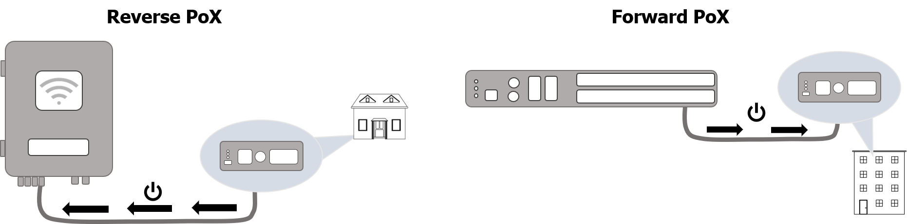
Power over X (PoX™) is a ReadyLinks technology that applies electric power over any cable. This allows you to power the ReadyLinks client device without the need for a local power source. Additionally, the client device will convert the additional power provided by PoX and output PoE/PoE+ depending on its capabilities.
GL-24xT-P600D# configure terminal
GL-24xT-P600D(config)# interface ethernet Ghn1
GL-24xT-P600D(Ghn1)# power inline poe-mode
mode - poe, poe-plus, poe-plus-plus, force_power#Max MAC learn
Max MAC learn specifies the maximum number of MAC addresses allowed to connect to a port. By default, there is no maximum set on any port.
GL-24xT-P600D# configure terminal
GL-24xT-P600D(config)# interface ethernet Ghn1
GL-24xT-P600D(Ghn1)# port-security maximum
mac-maxmum - 1-1024#Port status and counters
show interface status gives a one-line summary of every port: admin state, link, negotiation, speed, duplex, flow control, MAC learning, rate limits, isolation (protected), MTU, and max MAC learn. Use show interface ethernet <port> for a single port.
show interface counters ethernet <port> shows good and bad packets in each direction, drops, collisions, a unicast/multicast/broadcast breakdown, and a packet size histogram. Climbing bad-packet or drop counts point to cabling, duplex, or congestion problems. Use clear counters from the configuration view to reset the counters before you test.
GL-24xT-P600D# show interface status

    PORT         DESC           /STATE   /LINK/NEGO /SPEED /DUPLEX/FLOW-CONTROL/ LEARN /INGRESS /EGRESS  /PROTECTED/ MTU /MAXLEARN
--------------------------------------------------------------------
Ghn1         Ghn1           /enabled /down/   - /  -   /  -   /     -      / enable/disable /disable / enable  /1518 /disable
Ghn2         Ghn2           /enabled /down/   - /  -   /  -   /     -      / enable/disable /disable / enable  /1518 /disable
...
RJ45/G1      RJ45/G1        /enabled /down/force/1000M/ full /     -      / enable/disable /disable / disable /9216 /disable
Fiber/G1     Fiber/G1       /enabled /down/force/10000M/ full /     -      / enable/disable /disable / disable /9216 /disable
GL-24xT-P600D# show interface counters ethernet Ghn1
PORT        :  Ghn1
TXGOODPKTS
  H32bits   :  0
  L32bits   :  6512
TXBADPKTS   :  0
RXGOODPKTS
  H32bits   :  0
  L32bits   :  5417
RXBADPKTS   :  0
TXABORT     :  0
COLLISION   :  0
DROPPKT     :  0
...
GL-24xT-P600D# configure terminal
GL-24xT-P600D(config)# clear counters
Port statistics have been cleared.#Port configuration
These commands are entered in the port view (interface ethernet <port>):
- shutdown / no shutdown: Administratively disables or enables the port.
- description: A label of 3-32 characters, such as a unit number or the device connected. Descriptions make status output and troubleshooting much easier.
- speed / duplex: Force the speed (
10,100,1000,10000) or duplex (full,half), or leave them onauto(default). Force these settings only to match a device that doesn't auto-negotiate, and force both ends the same way to avoid duplex mismatches. These settings mainly apply to the RJ45 and Fiber ports, because G.hn port rates are set by the G.hn link (see G.hn link status). - flow-control: Enables 802.3x pause frames (disabled by default).
- mtu: Sets the maximum frame size.
no mturestores the default of 9216 bytes. - learning: MAC address learning is enabled by default. Disabling it causes traffic to that port's devices to be flooded.
GL-24xT-P600D# configure terminal
GL-24xT-P600D(config)# interface ethernet Fiber/G1
GL-24xT-P600D(Fiber/G1)# description ra300101001
Port description has been created successfully.
GL-24xT-P600D(Fiber/G1)# speed 1000
speed configured at 1000Mbps on Fiber/G1
GL-24xT-P600D(Fiber/G1)# no speed
Speed has been fixed auto on Fiber/G1
GL-24xT-P600D(Fiber/G1)# mtu 1518
Configuration has been completed successfully!
GL-24xT-P600D(Fiber/G1)# flow-control
Flow-control is enabled on Fiber/G1
GL-24xT-P600D(Fiber/G1)# shutdown
Port Fiber/G1 shut down.
GL-24xT-P600D(Fiber/G1)# no shutdown
Port Fiber/G1 has been enable.#QoS
#QoS port priority and DSCP
Quality of Service (QoS) makes sure latency-sensitive traffic such as voice, video conferencing, and building controls is forwarded ahead of bulk traffic when a link is congested. Each frame is assigned an 802.1p priority (CoS 0-7), which maps to one of eight output queues. Higher queues are serviced first, depending on the queue scheduling mode.
- Port priority: Sets the default priority (0-7, default 0) for frames received on a port. Use it on ports dedicated to one kind of device, for example a port with VoIP phones.
- DSCP:
qos dscp-mutationmakes a port classify traffic by the DSCP value in the IP header. Useqos map dscp <0-63> to cos <0-7>to set how each DSCP value maps to a priority, for example DSCP 46 (EF, voice) to CoS 5. - CoS-to-queue map:
qos cos-local-precedence-mapchanges which queue each CoS value uses.
GL-24xT-P600D# configure terminal
GL-24xT-P600D(config)# interface ethernet Ghn5
GL-24xT-P600D(Ghn5)# priority 5
Untagged packet default priority has been set 5 on port Ghn5
GL-24xT-P600D(Ghn5)# qos dscp-mutation
Dscp has been enabled on port Ghn5.
GL-24xT-P600D(Ghn5)# end

GL-24xT-P600D# configure terminal
GL-24xT-P600D(config)# qos map dscp 46 to cos 5
The configuration succeeds.
GL-24xT-P600D(config)# end
GL-24xT-P600D# show qos interface ethernet Ghn5
GL-24xT-P600D# show qos map dscp cos
GL-24xT-P600D# show qos cos-local-precedence-map
cos-local-precedence-map:
cos(802.1p)     :0   1   2   3   4   5   6   7
queue :0 1 2 3 4 5 6 7#QoS queue scheduling
The queue scheduler decides how the eight output queues share a congested port:
- strict-priority: Always empties the highest queue first. This gives the lowest latency for top-priority traffic, but heavy high-priority traffic can starve the lower queues.
- wrr (Weighted Round Robin): Each queue gets a share of bandwidth based on its weight (0-127). A weight of 0 makes that queue strict-priority.
- wdrr (Weighted Deficit Round Robin): Like WRR, but accounts for packet size so bandwidth is shared more evenly.
Use no qos queue-scheduler to restore the default and show qos queue-scheduler to verify.
GL-24xT-P600D# configure terminal
GL-24xT-P600D(config)# qos queue-scheduler wrr 1 2 3 4 5 6 7 8
The configuration is successful.
GL-24xT-P600D(config)# end
GL-24xT-P600D# show qos queue-scheduler
Queue scheduling mode: weighted round robin
weight of queue 0: 1
weight of queue 1: 2
weight of queue 2: 3
weight of queue 3: 4
weight of queue 4: 5
weight of queue 5: 6
weight of queue 6: 7
weight of queue 7: 8#Egress traffic limit
Egress limit is a switch-wide rate limit for a specific type of traffic, matched by EtherType (IP, ARP, or a hex value such as 0x0800) and, optionally, IP protocol (TCP, UDP, IGMP, ICMP, or a protocol number). It's useful for capping traffic that should never be heavy, such as ICMP or ARP, so it can't consume a link during a flood.
Rate (kbps) and burst (KB) each range from 0-999. This is separate from the per-port Port rate limit configuration. Note that the show command uses an underscore: show egress_limit.
GL-24xT-P600D# configure terminal
GL-24xT-P600D(config)# egress-limit add rate 500 burst 900 ethertype 0x0800 ip-protocol ICMP
GL-24xT-P600D(config)# end
GL-24xT-P600D# show egress_limit
Index    ethertype        IP protocol      rate            burst
  1       IP               ICMP        500kbps         900kbytes
GL-24xT-P600D# configure terminal
GL-24xT-P600D(config)# egress-limit no ethertype 0x0800 ip-protocol ICMP#Monitoring
#SNMP
SNMP lets a network monitoring system (NMS) poll the switch for status and counters and receive traps, for example when a port goes up or down. Set the system name, location, and contact so the switch is easy to identify in your NMS.
- SNMP v1/v2c: Uses community strings with read-only (
ro) or read-write (rw) access. Avoid the well-known namespublicandprivate, and grantrwonly when necessary. - SNMP v3: Uses named users with authentication (
md5orsha) and encryption (desoraes). Passwords must be 9-15 characters. Use v3 with SHA and AES wherever your NMS supports it. - Traps: Enable traps globally with
snmp-server trapsand add one or more trap destinations withsnmp-server host. Link up/down traps can also be turned on or off per port.
GL-24xT-P600D# configure terminal
GL-24xT-P600D(config)# snmp-server name GL24-Bldg-A
GL-24xT-P600D(config)# snmp-server location Minneapolis-MDF
GL-24xT-P600D(config)# snmp-server community n0c-r3ad v2c ro
SNMP agent user has been added successfully.
GL-24xT-P600D(config)# snmp-server user nocuser ro auth-alogrithm sha auth-password 1234567890 priv-alogrithm aes priv-password 1234567890
SNMP agent user has been added successfully.
GL-24xT-P600D(config)# snmp-server traps
Enable global traps successfully!
GL-24xT-P600D(config)# snmp-server host 192.168.0.111
Add traps-host successfully!
GL-24xT-P600D(config)# end
GL-24xT-P600D# show snmp-server community
GL-24xT-P600D# show snmp-server user
GL-24xT-P600D# show snmp-server host
GL-24xT-P600D# show snmp-server traps-status#RMON
RMON (Remote Monitoring) lets the switch watch its own counters and act on thresholds without constant polling from an NMS. An RMON setup has three parts:
- Events: What happens when an alarm fires:
none,log,trap, orlog-trap. - Alarms: Sample a MIB counter at an interval, as an
absolutevalue or adelta(the change since the last sample), and trigger events when it crosses a rising or falling threshold. Common counters include InOctets (.1.3.6.1.2.1.2.2.1.10.<port>), InErrors (.1.3.6.1.2.1.2.2.1.14.<port>), and RMON broadcast packets (.1.3.6.1.2.1.16.1.1.1.6.<port>). The startup type is1(rising),2(falling), or3(rising-falling). - History: Records port statistics in buckets at a set interval for later review.
Create events before the alarms that reference them. View results with show rmon event, show rmon alarm, show rmon history control, show rmon history table, and show rmon log.
GL-24xT-P600D# configure terminal
GL-24xT-P600D(config)# rmon
GL-24xT-P600D(rmon)# event index 1 type log-trap community n0c-r3ad description uplink-errors owner noc
Configuration completed successfully.
GL-24xT-P600D(rmon)# alarm index 1 variable .1.3.6.1.2.1.2.2.1.14.7 sample-type delta startup 1 rising 40 1 falling 30 1 interval 100 owner noc
Configuration completed successfully.
GL-24xT-P600D(rmon)# history index 5 interval 20 buckets 30 ethernet Ghn1 owner noc
Configuration completed successfully.
GL-24xT-P600D(rmon)# end
GL-24xT-P600D# show rmon alarm
GL-24xT-P600D# show rmon log
Index   Event       Time                       Description
--------- ----------    ---------------------             ------------------------------
1        1       Sep 11 14:44:10 2012   MIB Var:1.3.6.1.2.1.2.2.1.10.1.0,Absolu
te,Rising,Actual Val:51368660,Thresh.Set:5,Interval(sec):3#System logging
The switch keeps a local log of system events, such as logins (with source IP and method), configuration activity, and alarms. View it with show logging and clear it with clear logging. The local log is lost when the switch reboots, so send logs to a central syslog server for retention and correlation.
logging host sets the syslog server IP address, UDP port (default 514), and the log priority to send (3-7). Use show logging host to verify.
GL-24xT-P600D# show logging
2012/11/7 11:20:15 192.168.114.248 logins the systerm via WEB UI!
2012/11/7 11:16:44 192.168.114.248 has logout the systerm via WEB UI!
2012/11/7 11:15:27 192.168.112.253 logins the system via Telnet, level 3.
GL-24xT-P600D# configure terminal
GL-24xT-P600D(config)# logging host 192.168.0.111 port 514 priority 5
Configuration completed successfully
GL-24xT-P600D(config)# end
GL-24xT-P600D# show logging host
  Log server information:
  Status      : Enabled
  IP address  : 192.168.0.111
  Port        : 514
  Priority    : 5
GL-24xT-P600D# configure terminal
GL-24xT-P600D(config)# clear logging
All logs have been cleared successfully.#G.hn settings
#G.hn link status
What sets ReadyLinks switches apart from standard L2 switches is their G.hn (ReadyLink) ports. They carry Ethernet over existing coax or twisted-pair wiring to a ReadyLinks client device. Each G.hn port on the switch is a Domain Master (DM), and the client device at the other end is an End Point (EP). In CLI output, Ghn1 is the switch port and Ghn1.1 is the client connected to it.
show ghn interface is the most important G.hn troubleshooting command. For each port it shows link state, local and remote MAC address, physical downstream/upstream rate, estimated wire length, and estimated throughput. Low rates on a short run usually point to a wiring problem such as a splitter, a bad connector, or noise. show ghn summary adds each node's name, serial number, role, IP address, firmware version, and VectorBoost state.
GL-24xT-P600D# show ghn interface
Interface Master_ID Link Local_MAC      Remote_MAC     Physical_DS/US_Speed(Mbps) Wire_Length(m) Estimated_XPUT(Mbps) Estimated_XPUT_DS/US(Mbps)
------------------------------------------------------------------------
Ghn1.1    1         up   0013.ba19.170d 0013.ba0a.4c9e 1827/1804                  5(m)            1427(Mbps)          1074/455
Ghn2      2         down 0013.ba19.1007 0000.0000.0000 -/-                        -(m)           -(Mbps)
Ghn3      3         down 0013.ba19.170f 0000.0000.0000 -/-                        -(m)           -(Mbps)
...
GL-24xT-P600D# show ghn summary
INTERFACE|NODE NAME  |MAC ADDRESS        |SN          |DATE       |DOMAIN NAME  |ROLE  |NODE ID
         |DOMAIN ID |IP ADDRESS    |SYNC SIGNAL |MODE      |FIRMWARE_VERSION           |VECTORBOOST  |VECTORBOOST_TX
--------------------------------------------------------------------------------------------------------------------------------------------------------------
Ghn1     |GL-24xT    |0013.ba19.170d     |R3A0004000  |           |ReadyLinks   |DM    |1
         |0         |192.168.10.252|External    |SISO      |v7_8_r590+6_cvs R93        |Disabled     |Disabled
Ghn1.1   |IPC-2TC    |0013.ba0a.4c9e     |R3A0004102  |           |ReadyLinks   |EP    |2
         |0         |192.168.10.253|Internal    |SISO      |v7_8_r590+6_cvs R2         |Disabled     |Enabled
...#G.hn system and node information
show ghn system displays switch-wide G.hn settings: the system ID, G.hn slot state, VectorBoost state, SISO/MIMO mode and bandwidth, and the upstream/downstream ratio. Other commands look at individual nodes or the whole domain:
show ghn client <mac>: The client MAC addresses learned behind a G.hn node. Use it to see which subscriber devices are connected to an endpoint.show ghn temperature: The temperature of every G.hn node, with a max/min/average summary.show ghn statistics gap <1-30>: Rx/Tx packet counts and the increase over the sample gap, for each node.show ghn version,show ghn role,show ghn sn,show ghn node-name, andshow ghn sync-signal: Single-column views of the summary fields.
The G.hn system ID (1-240) is set with ghn system <id> and takes about 3 minutes to take effect.
GL-24xT-P600D# show ghn system
System profile ID: PTP
G.hn slot1 state : online
G.hn slot1 power : on
G.hn slot1 reset : on
G.hn slot2 state : online
G.hn slot2 power : on
G.hn slot2 reset : on
G.hn VectorBoost : disabled
G.hn mode        : SISO 200MHz
G.hn system ID   : 1
G.hn US/DS ratio : 30% : 70%
GL-24xT-P600D# show ghn client 0013.ba03.70cb
Index   Client MAC Address
1       54a0.507c.c435
GL-24xT-P600D# show ghn temperature
Interface MAC               Temperature
----------------------------------------
Ghn1      0013.ba19.170d    72.800000
Ghn1.1    0013.ba0a.4c9e    64.800000
...
----------------------------------------
Local nodes temperature summery:

Max          Min          AVG
74.330000 58.700000 68.302308#G.hn mode (SISO / MIMO)
G.hn can run over one wire pair or two:
- SISO (Single Input, Single Output): Uses one pair. Works over coax and single-pair wiring.
- MIMO (Multiple Input, Multiple Output): Uses two pairs at once for higher throughput. Use MIMO only where two pairs are available end to end.
The mode is set switch-wide. show ghn system shows the current mode. Because the G.hn links may retrain after the mode changes, make the change during a maintenance window.
GL-24xT-P600D# configure terminal
GL-24xT-P600D(config)# ghn mode MIMO
GL-24xT-P600D(config)# end
GL-24xT-P600D# show ghn system#G.hn long reach mode
Long reach mode tunes a G.hn link for cable runs longer than 150 meters. Mode 0 (default) gives better performance on runs shorter than 150 m. Mode 1 is for runs longer than 150 m. The setting is applied per node by MAC address.
To decide which nodes need it, check the Wire_Length column of show ghn interface (see G.hn link status). Enabling long reach on short runs can reduce throughput, so use it only where needed.
GL-24xT-P600D# show ghn longReachMode 0013.ba34.5617
Mode=0 (Better performance if less than 150 meters).
GL-24xT-P600D# configure terminal
GL-24xT-P600D(config)# ghn longReachMode 0013.ba34.5617 1
Set longReachMode successfully.#G.hn downstream ratio
G.hn links share the medium between directions. The downstream ratio sets the percentage of airtime given to downstream traffic (switch to client), and the rest goes upstream. The range is 20-80. The default split shown in show ghn system is 30% upstream and 70% downstream, which suits typical internet use where subscribers download more than they upload.
Lower the downstream ratio for deployments where the client side mostly sends data, such as IP cameras streaming video back to an NVR. Raise it for download-heavy deployments.
GL-24xT-P600D# configure terminal
GL-24xT-P600D(config)# ghn downstream ratio 50
The configuration of downstream ration completed successfully.
GL-24xT-P600D(config)# end
GL-24xT-P600D# show ghn system#VectorBoost
VectorBoost raises throughput on twisted-pair ReadyLinks lines by managing crosstalk between pairs in real time. Its compute engine can run locally on the switch or on a VectorBoost cloud server for high-density deployments. VectorBoost applies only to twisted-pair devices, not coax.
Use local to run the engine on the switch, server-ip to point the switch at a VectorBoost server, or disable to turn it off. show readyview vectorBoost and the VECTORBOOST columns of show ghn summary show its status. For engine states, requirements (including keeping VLAN 1 untagged on G.hn ports), and troubleshooting, see the VectorBoost guide.
GL-24xT-P600D# configure terminal
GL-24xT-P600D(config)# readyview vectorBoost local
GL-24xT-P600D(config)# readyview vectorBoost server-ip 10.1.100.11
The configuration of vectorBoost completed successfully.
GL-24xT-P600D(config)# end
GL-24xT-P600D# show readyview vectorBoost#G.hn spectrum notching
Spectrum notching attenuates a frequency range on a G.hn port. Use it to avoid interfering with, or being affected by, other services on the same wiring, or to work around a known noise source. Specify the start and stop frequency, the attenuation depth (1-40 dB), and the port. Remove a notch with the matching no ghn spectrum command. show ghn user_notch lists the notches configured on each node.
Notching reduces the spectrum available to the link, so expect lower throughput on that port. Apply notches only where needed and check show ghn interface before and after.
GL-24xT-P600D# configure terminal
GL-24xT-P600D(config)# ghn spectrum startfrequency 5000 stopfrequency 17000 depth 10 ethernet Ghn1
The configuration of spectrum filtering completed successfully.
GL-24xT-P600D(config)# no ghn spectrum startfrequency 5000 stopfrequency 17000 ethernet Ghn1
The configuration of spectrum filtering completed successfully.
GL-24xT-P600D(config)# end
GL-24xT-P600D# show ghn user_notch#G.hn node management and firmware
G.hn nodes (the switch's domain masters and the client endpoints) run their own firmware, separate from the switch firmware. show ghn version and show ghn upgrade list each node's firmware version and upgrade state.
- Upgrade:
ghn upgradeupgradeslocal(the switch's own G.hn nodes),remote(client endpoints),all, a singlenode <mac>, orauto(upgrade nodes automatically). Firmware images can be loaded from TFTP withghn tftp, specifying whether the image is forDMorEPnodes. Upgrade progress is reported to the system log. - Restart / reset:
ghn restart <mac>reboots a single node, andghn reset node <mac>resets it. Both are useful for recovering an unresponsive client without a site visit. - Node IP:
ghn ipconfigsets a node's management address (DHCP or static, IPv4 or IPv6). - Multicast snooping:
ghn multicastsets a node's multicast snooping type (IGMP,MLD,IGMP&MLD, orNONE) to match your IGMP Snooping design.
GL-24xT-P600D# configure terminal
GL-24xT-P600D(config)# ghn tftp 192.168.0.230 firmware firmwarev398+5+9d mode DM
Loading firmware, please wait...
Firmware has been loaded successfully.
GL-24xT-P600D(config)# ghn upgrade remote
The configuration is successful.
The system is upgrading the device(s).
Please wait... and check the upgraded status to syslog.
GL-24xT-P600D(config)# ghn restart 0013.ba02.005e
Reboot ghn node successful!
GL-24xT-P600D(config)# ghn ipconfig mac 0013.ba34.5601 dhcp ipv4
Set ghn node ip successful!
GL-24xT-P600D(config)# ghn multicast mac 0013.ba18.0804 snooping-type IGMP
set Multicast Snooping Type IGMP success!
GL-24xT-P600D(config)# end
GL-24xT-P600D# show ghn upgradeLast updated October 2, 2026