Ethernet, PoE, and cabling
Link speeds, auto-negotiation and duplex, copper and fibre cable types, distance limits, Power over Ethernet budgets, and sensible physical topologies.
Most "network" problems in the field are physical: a bad crimp, a run that is too long, a PoE budget that is exhausted. This page covers the Layer 1 fundamentals that make everything above them possible.
#Ethernet speeds
Ethernet has kept the same frame format for decades while the speed has gone up by orders of magnitude. The speeds you will meet on a modern access network:
| Name | Speed | Copper cable | Max copper distance | Where you see it |
|---|---|---|---|---|
| Fast Ethernet | 100 Mbit/s | Cat 5 or better | 100 m | Old phones, cameras, printers |
| Gigabit Ethernet | 1 Gbit/s | Cat 5e or better | 100 m | The default for everything |
| 2.5GBASE-T | 2.5 Gbit/s | Cat 5e or better | 100 m | Wi-Fi 6/6E access points |
| 5GBASE-T | 5 Gbit/s | Cat 6 or better | 100 m | High-end access points |
| 10GBASE-T | 10 Gbit/s | Cat 6A | 100 m (Cat 6: 55 m) | Uplinks, servers |
| 10G / 25G / 100G | 10–100 Gbit/s | Fibre (SFP+ / SFP28 / QSFP28) | 300 m to 40 km+ depending on optics | Uplinks between switches and buildings |
A link always runs at the fastest speed both ends and the cable support. A gigabit switch port connected to a 100 Mbit camera runs at 100 Mbit. That is normal and not a fault.
#Auto-negotiation and duplex
When a cable is connected, both ends exchange pulses to agree on a speed and a duplex mode. Full duplex means both sides can send at the same time; half duplex means they take turns, which halves effective throughput and causes collisions.
Every modern device auto-negotiates full duplex at the fastest common speed. The one thing that still goes wrong is a duplex mismatch: one side is manually forced to a fixed speed and duplex while the other is left on auto. The auto side can't negotiate, falls back to half duplex, and the link "works" but is slow and racks up errors. The fix is to set both ends to auto. Only force a speed if the other end is a legacy device that can't negotiate.
Symptoms of a duplex mismatch or a bad cable look the same from the dashboard: the port is up, but the error and discard counters climb. ReadyView shows these counters per port; see switchport.
On the CLI, show interface status lists link state, negotiation, speed and duplex for every port, and the per-port counters show bad packets and collisions. Speed and duplex are set in interface mode and should normally be left on auto.
GL-24xT-P600D# show interface status
GL-24xT-P600D# show interface counters ethernet RJ45/G1
GL-24xT-P600D# configure terminal
GL-24xT-P600D(config)# interface ethernet RJ45/G1
GL-24xT-P600D(RJ45/G1)# description Front desk PC
GL-24xT-P600D(RJ45/G1)# speed auto
GL-24xT-P600D(RJ45/G1)# duplex auto
GL-24xT-P600D(RJ45/G1)# end
GL-24xT-P600D(config)# write
speed accepts 10, 100, 1000 or auto; duplex accepts half, full or auto. On coax models the G.hn ports don't take speed or duplex settings at all; only the RJ45 and fibre uplinks do.
#Copper cabling
Twisted-pair copper is categorised by how much bandwidth it can carry cleanly over 100 metres:
| Category | Rated for | Notes |
|---|---|---|
| Cat 5 | 100 Mbit/s | Obsolete. Replace if found. |
| Cat 5e | 1 Gbit/s (2.5G usually works) | Still common; fine for most access ports. |
| Cat 6 | 1 Gbit/s to 100 m, 10G to 55 m | The current minimum for new installs. |
| Cat 6A | 10 Gbit/s to 100 m | Recommended for new installs, access points, and anywhere PoE++ will run. |
| Cat 7 / 8 | Specialist | Rarely justified; Cat 6A plus fibre covers the same ground. |
Rules that hold regardless of category:
- 100 metres is the limit from switch port to device, including both patch leads. Exceeding it produces a link that works at short cable lengths in testing and fails intermittently in the field. Use a switch, a fibre link, or a media converter for longer runs.
- Both ends must be terminated to the same standard (T568A or T568B). Mixed terminations on the same cable make a crossover cable, which gigabit ports will tolerate but 100 Mbit devices won't.
- Use solid-core cable for in-wall runs and stranded for patch leads. Solid core is cheaper and lower loss but breaks if flexed repeatedly.
- Keep away from mains cables and fluorescent fittings. Run parallel to power only where unavoidable, and cross at right angles.
- Test every run with a certifier after installation, not just a continuity tester. A cable can pass continuity and still fail at gigabit speeds.
#Fibre
Fibre carries light rather than electricity, so it is immune to electrical interference, carries no ground potential between buildings, and goes much further than copper.
| Type | Core | Typical reach | Use |
|---|---|---|---|
| Multimode (OM3 / OM4) | 50 µm | 300–550 m at 10G | Inside a building, between floors or rooms |
| Single-mode (OS2) | 9 µm | 10–40 km+ | Between buildings, campus, metro |
Fibre plugs into a switch through a pluggable transceiver (SFP for 1G, SFP+ for 10G, SFP28 for 25G). The transceiver must match the fibre type and the one at the far end: a multimode optic will not talk to a single-mode optic even if the connectors fit. Always use fibre for any run between buildings; copper between buildings is a lightning and ground-loop hazard.
#Power over Ethernet
PoE delivers DC power over the same twisted-pair cable that carries data, so access points, phones, cameras, and small switches need no separate power supply. The switch (the PSE, power sourcing equipment) negotiates with the device (the PD, powered device) and only applies power once it has confirmed something PoE-capable is connected. Plugging a non-PoE laptop into a PoE port is safe.
| Standard | Common name | Power at the switch port | Power available at the device | Typical devices |
|---|---|---|---|---|
| 802.3af | PoE | 15.4 W | 12.95 W | Phones, basic cameras, small APs |
| 802.3at | PoE+ | 30 W | 25.5 W | Wi-Fi 5/6 access points, PTZ cameras |
| 802.3bt Type 3 | PoE++ / 4PPoE | 60 W | 51 W | Wi-Fi 6E/7 APs, video displays, small switches |
| 802.3bt Type 4 | PoE++ | 90–100 W | 71 W | LED lighting, laptops, building controllers |
Two things catch people out:
- The PoE budget. A switch has a total amount of power it can supply across all ports, which is usually far less than every port at maximum. A 24-port switch with a 370 W budget can run 24 phones, or 12 PoE+ access points, but not 24 PoE+ access points. When the budget is exceeded the switch drops power to the lowest-priority ports, and devices mysteriously reboot. ReadyView shows per-port power draw and the remaining budget; see switch settings.
- Cable loss. The difference between the two power columns above is lost as heat in the cable. Thin, long, or bundled cables lose more. For PoE++ runs, use Cat 6A and avoid tightly bundling many powered cables together.
On a PoE-capable GL-series switch, show power reports the budget and the draw on each port. Per port you can set the PoE class and a priority that decides which ports lose power first when the budget is exceeded. force_power applies power without the negotiation handshake, for the rare device that needs it; use it only on a port you've checked.
GL-24xT-P600D# show power
GL-24xT-P600D# configure terminal
GL-24xT-P600D(config)# power inline max-power 370
GL-24xT-P600D(config)# interface ethernet RJ45/G1
GL-24xT-P600D(RJ45/G1)# power inline poe-mode poe-plus
GL-24xT-P600D(RJ45/G1)# power inline priority critical
GL-24xT-P600D(RJ45/G1)# end
GL-24xT-P600D(config)# interface ethernet RJ45/G24
GL-24xT-P600D(RJ45/G24)# no power inline poe-mode
GL-24xT-P600D(RJ45/G24)# end
GL-24xT-P600D(config)# write
poe-mode is one of poe, poe-plus, poe-plus-plus or force_power; priority is low, high or critical. no power inline poe-mode turns PoE off on a port. See PoE settings in the dashboard.
#Physical topology
How switches are cabled to each other matters more than any VLAN setting for reliability.
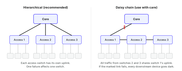
- Hierarchical (star / tree). Every access switch has its own uplink to a core or distribution switch. A failed link or switch affects only its own ports, and each uplink carries only its own switch's traffic. This is the right default.
- Daisy chain. Access switches are linked in a line, each one's uplink going through the previous one. It is cheaper and sometimes the only option in a long building, but all downstream traffic funnels through the first switch's uplink, and any failure near the top takes out everything below it. If you must chain, keep chains short, use the fastest uplinks you can, and upgrade firmware one switch at a time from the far end back (see firmware best practices).
- Ring with STP. A chain whose last switch is also cabled back to the core. Spanning tree blocks one link in normal operation and unblocks it if another fails, giving a chain's cost with much better resilience.
Whatever the topology, uplinks should be the fastest ports on the switch (10G SFP+ where available) and, where budget allows, bundled in a LAG for redundancy.
LLDP lets each switch report what is plugged into each port, which turns a cabling diagram into something you can verify from the CLI instead of walking the closet. Enable it globally, then list neighbours.
GL-24xT-P600D# configure terminal
GL-24xT-P600D(config)# lldp
GL-24xT-P600D(config)# write
GL-24xT-P600D(config)# exit
GL-24xT-P600D# show lldp neighbor_information
GL-24xT-P600D# show lldp statistics ethernet Fiber/G1
ReadyView uses the same LLDP data to draw daisy chains and uplinks in the topology view.
#Link lights
The LEDs on a port are the quickest diagnostic there is:
| LED state | Meaning |
|---|---|
| Off | No link. Cable, far-end device, or port is down. |
| Solid green or amber | Link established. Colour usually indicates speed (green = gigabit, amber = 100 Mbit on many switches). |
| Blinking | Traffic passing. |
| Link light on but no traffic ever | Layer 1 is fine; look at VLANs, DHCP, or the device. |
A port that flaps up and down every few seconds usually has a marginal cable, a PoE device that can't get enough power, or a far-end device rebooting in a loop.
Next: Layer 2 security covers the switch features that protect the VLANs running over these links.
Last updated October 5, 2026