Switching and VLANs
What a switch does, why networks are split into VLANs, how tagged and untagged ports work, and how traffic gets between VLANs.
A switch is the device most of the ReadyLinks documentation is about. This page explains what it does on its own, and then how VLANs turn one switch into several logical networks.
#What a switch does
A switch connects devices on the same local network. It learns which MAC address is on which port by watching the source address of every frame, and then forwards each frame only to the port where its destination lives. How data moves covers the mechanics in detail.
Three properties follow from that:
- Full bandwidth per port. Because frames go only where they need to, two devices talking on ports 1 and 2 don't slow down a conversation between ports 3 and 4. A switch is not a shared medium.
- Zero configuration for basic use. Plug things in and they can talk. Everything on this page is about controlling who can talk to whom, not about making it work at all.
- One big broadcast domain. Without further configuration every port hears every broadcast. That is the problem VLANs solve.
#Why VLANs exist
A VLAN (Virtual LAN) is a way of telling a switch "treat these ports as if they were on a separate switch". Frames in VLAN 20 are never forwarded to a port in VLAN 30, broadcasts in VLAN 20 never reach VLAN 30, and a device in VLAN 20 can't ARP for a device in VLAN 30. Each VLAN is its own broadcast domain and, almost always, its own IP subnet.
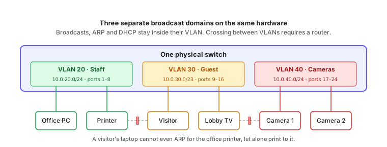
The reasons to do this:
| Reason | Example |
|---|---|
| Security | Guest Wi-Fi users can't see staff file servers or printers. Cameras can't reach anything except the recorder. |
| Containment | A broadcast storm, a rogue DHCP server, or a chatty device only affects its own VLAN. |
| Scale | Keeping each broadcast domain to a few hundred devices keeps ARP and DHCP traffic negligible. |
| Policy | Different VLANs can have different bandwidth limits, firewall rules, DHCP settings, and quality-of-service treatment. |
| Flexibility | Moving a device from "staff" to "guest" is a settings change on the port, not a cabling change. |
In multi-tenant buildings — hotels, apartments, student housing — it is common to put every unit in its own VLAN so neighbours are completely isolated from each other. ReadyLinks subscriber management is built on exactly that pattern.
#VLAN IDs
Each VLAN is identified by a number from 1 to 4094. A few conventions are worth knowing:
- VLAN 1 is the default on every switch. All ports start in it. Best practice is to move real traffic off VLAN 1 and leave it unused, because it is the one every attacker and every misconfigured device will try first.
- There is no technical meaning to the numbers, but a consistent scheme across sites saves enormous confusion. Many organisations match the VLAN ID to the third octet of the subnet (VLAN 20 ↔
10.0.20.0/24). - A management VLAN carries the switches' own addresses, so administrative access is separated from user traffic.
#Access ports and trunk ports
Every switch port is in one of two modes.
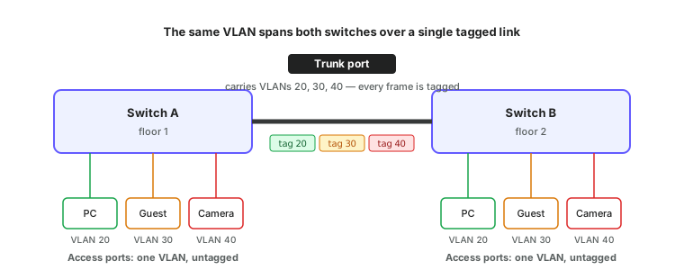
An access port belongs to exactly one VLAN. Frames arrive and leave without any VLAN information in them; the switch adds the VLAN membership internally based on the port. This is what you use for endpoints: a PC, a phone, a camera, a printer. The device doesn't know or care which VLAN it is in.
A trunk port carries several VLANs over one cable. To keep them apart, every frame on a trunk gets a small 802.1Q tag inserted into its Ethernet header saying which VLAN it belongs to. The switch at the other end reads the tag, removes it, and places the frame in the right VLAN. Trunks are used between switches, to routers and firewalls, and to wireless access points that broadcast several networks.
#Tagged, untagged, and the native VLAN
Vendors use slightly different words for the same thing. The mapping is:
| Concept | Also called | Meaning |
|---|---|---|
| Untagged VLAN on a port | Access VLAN, PVID, native VLAN | Frames arriving with no tag are placed in this VLAN; frames leaving in this VLAN have no tag. A port has at most one. |
| Tagged VLANs on a port | Allowed VLANs, trunk VLANs | VLANs the port will carry with a tag. A port can have many. |
| Access port | Untagged port | One untagged VLAN, no tagged VLANs. |
| Trunk port | Tagged port, uplink | Usually several tagged VLANs, optionally one untagged (native) VLAN. |
The native VLAN is the one untagged VLAN on a trunk. It exists so that devices which don't understand tags (an old printer, a switch's own management traffic during boot) still work on a trunk port. Both ends of a trunk must agree on the native VLAN, or frames silently end up in the wrong network.
#Configuring VLANs on a ReadyLinks switch
The ReadyLinks CLI splits VLAN configuration across two modes, which trips up people used to other vendors. Membership (which ports carry a VLAN, tagged or untagged) is set inside VLAN mode. The PVID (which VLAN untagged frames arriving on a port belong to) and the link type are set inside interface mode. An access port needs both: untagged membership in its VLAN, and a PVID of that VLAN.
GL-24xT-P600D# configure terminal
GL-24xT-P600D(config)# vlan 20
GL-24xT-P600D(vlan20)# name Staff
GL-24xT-P600D(vlan20)# switchport untagged ethernet RJ45/G1 to ethernet RJ45/G8
GL-24xT-P600D(vlan20)# switchport tagged ethernet Fiber/G1
GL-24xT-P600D(vlan20)# end
GL-24xT-P600D(config)# interface ethernet RJ45/G1
GL-24xT-P600D(RJ45/G1)# switchport link-type access
GL-24xT-P600D(RJ45/G1)# switchport pvid 20
GL-24xT-P600D(RJ45/G1)# end
GL-24xT-P600D(config)# interface ethernet Fiber/G1
GL-24xT-P600D(Fiber/G1)# switchport link-type trunk
GL-24xT-P600D(Fiber/G1)# end
GL-24xT-P600D(config)# write
GL-24xT-P600D(config)# exit
GL-24xT-P600D# show vlan all
GL-24xT-P600D# show vlan 20
GL-24xT-P600D# show interface switchport ethernet RJ45/G1
Notes on the syntax:
vlan 20creates the VLAN if it doesn't exist and enters VLAN mode.vlan 20 to vlan 29creates a range.- VLAN-mode membership commands accept a port range (
ethernet RJ45/G1 to ethernet RJ45/G8) and a VLAN range (switchport tagged ethernet Fiber/G1 to vlan 29). Interface mode takes one port at a time. switchport link-type trunk permit vlan alladds a trunk to every VLAN at once. Leaving it off and tagging VLANs individually is how you prune a trunk.switchport link-type hybridallows a mix of tagged and untagged VLANs on one port, which is what a phone-plus-PC desk port needs.endreturns to config mode;exitdrops all the way to the top-level prompt.writesaves.no vlan 20deletes a VLAN;no switchport tagged ethernet Fiber/G1(in VLAN mode) removes a port from it.
#Getting between VLANs
Separating traffic is only half the job. Staff still need to reach the internet, the camera VLAN still needs to talk to the recorder, and administrators need to reach the management VLAN from their desks. Since switches won't forward between VLANs, a router has to.
There are two ways to arrange that:
- Router on a stick. A trunk from the switch to an external router or firewall. The router has one logical interface per VLAN and routes between them. Simple, but every inter-VLAN packet crosses the trunk twice, so the trunk becomes the bottleneck.
- Layer 3 switch. The switch itself has an IP interface in each VLAN (often called an SVI, switch virtual interface) and routes between them in hardware. Inter-VLAN traffic never leaves the switch. This is how ReadyLinks GLx switches are normally deployed.
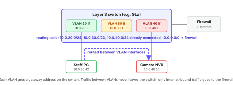
Either way, the default gateway you hand out via DHCP in each VLAN is the router's address in that VLAN. Once routing exists, access control lists (ACLs) or firewall rules decide which VLANs may talk to which. A typical policy is: everything may reach the internet; staff may reach cameras; guests may reach nothing internal; nothing may reach management except administrators.
On a GL-series switch, each VLAN's gateway is an address on a VLAN interface. Enable IP routing and give each VLAN an interface:
GL-24xT-P600D# configure terminal
GL-24xT-P600D(config)# interface vlan 20
GL-24xT-P600D(vlan-interface20)# ip address 10.0.20.1 255.255.255.0
GL-24xT-P600D(vlan-interface20)# end
GL-24xT-P600D(config)# interface vlan 40
GL-24xT-P600D(vlan-interface40)# ip address 10.0.40.1 255.255.255.0
GL-24xT-P600D(vlan-interface40)# end
GL-24xT-P600D(config)# write
GL-24xT-P600D(config)# exit
GL-24xT-P600D# show vlan interface
GL-24xT-P600D# show ip routing-table#Loops and spanning tree
If two switches are connected by two cables, or a cable is accidentally looped from one port of a switch back into another, a broadcast will circle forever and multiply until the network collapses. This is a broadcast storm, and it will take an entire broadcast domain down in seconds.
Spanning Tree Protocol (STP, and its faster successor RSTP) exists to prevent it. Switches running STP discover every loop and deliberately block one port in each, leaving a loop-free tree. If an active link fails, a blocked port is unblocked within a few seconds to restore connectivity. STP is on by default on ReadyLinks switches and should stay on.
Two related features are worth enabling on every access port:
- BPDU guard shuts a port down if a switch is detected on it, which stops someone plugging in an unmanaged switch and creating a loop.
- Storm control rate-limits broadcasts on a port so that one faulty device can't flood the VLAN.
On a ReadyLinks switch, spanning tree is enabled globally and spanning-tree edge marks ports that only ever have endpoints on them, so they forward immediately instead of waiting through the listening and learning states. BPDU guard is a global setting here, not per port.
GL-24xT-P600D# configure terminal
GL-24xT-P600D(config)# spanning-tree
GL-24xT-P600D(config)# spanning-tree mode rstp
GL-24xT-P600D(config)# spanning-tree bpdu-guard
GL-24xT-P600D(config)# interface ethernet RJ45/G1
GL-24xT-P600D(RJ45/G1)# spanning-tree edge
GL-24xT-P600D(RJ45/G1)# end
GL-24xT-P600D(config)# write
GL-24xT-P600D(config)# exit
GL-24xT-P600D# show spanning-tree
GL-24xT-P600D# show spanning-tree ethernet Fiber/G1#Link aggregation
When one cable isn't enough between two switches, several can be bundled into a LAG (link aggregation group, also called a port channel or, when using the standard negotiation protocol, LACP). The bundle behaves as one logical link with the combined bandwidth and keeps working if a member cable fails. Both ends must be configured for it; a LAG on one side and plain ports on the other creates a loop that STP will then block.
On a ReadyLinks switch a group is created in config mode and ports join it from interface mode. mode manual bundles the ports with no negotiation; mode static uses LACP, in which case enable lacp globally and set each member to active on at least one end.
GL-24xT-P600D# configure terminal
GL-24xT-P600D(config)# lacp
GL-24xT-P600D(config)# link-aggregation group 1 mode static
GL-24xT-P600D(config)# link-aggregation group 1 description Uplink-to-core
GL-24xT-P600D(config)# interface ethernet Fiber/G1
GL-24xT-P600D(Fiber/G1)# link-aggregation group 1
GL-24xT-P600D(Fiber/G1)# lacp mode active
GL-24xT-P600D(Fiber/G1)# end
GL-24xT-P600D(config)# interface ethernet Fiber/G2
GL-24xT-P600D(Fiber/G2)# link-aggregation group 1
GL-24xT-P600D(Fiber/G2)# lacp mode active
GL-24xT-P600D(Fiber/G2)# end
GL-24xT-P600D(config)# write
GL-24xT-P600D(config)# exit
GL-24xT-P600D# show link-aggregation summary
GL-24xT-P600D# show link-aggregation verbose 1
Add the VLANs to the member ports as usual; the group inherits them. Up to 13 groups are supported. Joining a LAG over an in-band uplink can fail on the first attempt while the link renegotiates; retrying the same command succeeds.
#Summary
| Term | One line |
|---|---|
| VLAN | A separate broadcast domain inside a switch, identified by a number 1–4094. |
| Access port | One untagged VLAN; used for endpoints. |
| Trunk port | Several tagged VLANs on one cable; used between network devices. |
| 802.1Q tag | The four bytes added to a frame on a trunk to say which VLAN it belongs to. |
| Native VLAN | The single untagged VLAN on a trunk. Must match at both ends. |
| SVI | The switch's own IP interface in a VLAN; the VLAN's default gateway on a Layer 3 switch. |
| STP | Blocks redundant links so loops can't form; unblocks them if a link fails. |
| LAG | Several cables acting as one link for bandwidth and redundancy. |
Next: VLANs in depth covers design patterns, management and voice VLANs, port isolation, and the attacks that target VLAN boundaries.
Last updated October 5, 2026