How data moves
Frames, packets, MAC addresses, ARP, and the difference between switching and routing.
Every byte that crosses a network is wrapped, forwarded, unwrapped, and re-wrapped several times before it reaches its destination. This page follows one piece of data through that process and names each thing it touches along the way.
#Frames and packets
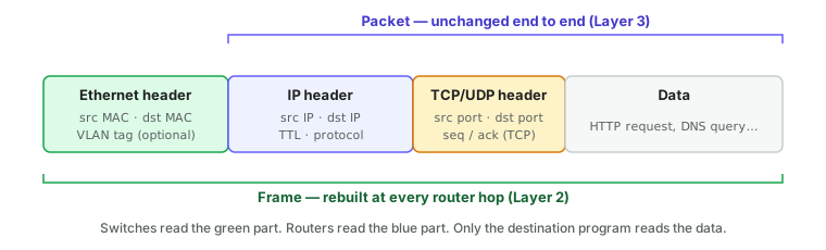
Data is never sent as a continuous stream. It is chopped into chunks, and each chunk is wrapped in headers that say where it came from and where it is going. Two of those wrappers matter here:
- A packet is a chunk of data with an IP header on the front. The IP header carries the source and destination IP addresses. A packet is built once by the sender and survives unchanged (apart from a hop counter and NAT) all the way to the destination.
- A frame is a packet with an Ethernet header on the front. The Ethernet header carries the source and destination MAC addresses. A frame only lives for a single hop: every switch forwards it as-is, but every router discards it and builds a new one.
Think of a packet as a letter and a frame as the envelope. The letter is addressed to its final recipient. The envelope is addressed to the next post office.
#Switching: forwarding by MAC address
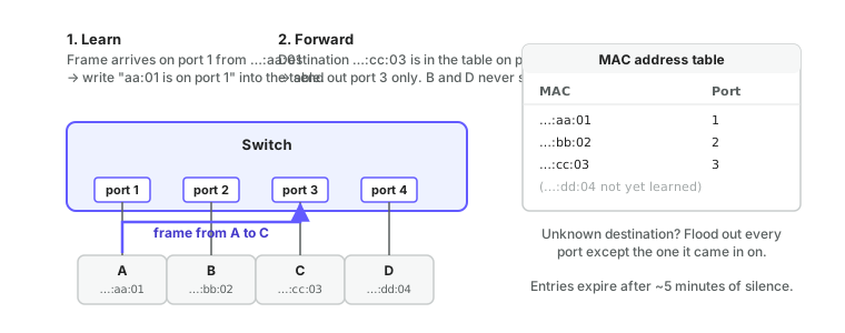
A switch has one job: deliver a frame to the port where the destination MAC address lives, and nowhere else.
It does this with a MAC address table (also called a CAM table or forwarding table). The table starts empty. Each time a frame arrives, the switch notes the source MAC and the port it arrived on, and writes that pairing into the table. That is called learning. Over a few seconds the switch builds a complete map of which device is on which port without anyone configuring anything.
When a frame arrives, the switch looks up the destination MAC:
| Lookup result | Action | Name |
|---|---|---|
| Found, on a different port | Send out that one port only | Forward |
| Found, on the same port it arrived on | Drop it; the destination already saw it | Filter |
| Not found | Send out every port except the one it arrived on | Flood |
Destination is ff:ff:ff:ff:ff:ff | Send out every port except the one it arrived on | Broadcast |
Flooding is what lets a switch work before its table is populated. Once the unknown device replies, the switch learns its port and stops flooding to it. Table entries expire after a few minutes of silence (300 seconds by default on most switches) so that a device moved to a new port is re-learned quickly.
You can see the MAC table on any ReadyLinks switch from the switch settings page in ReadyView, or from the CLI with show mac-address-table. It is the single most useful thing to look at when a device "isn't showing up": if the switch has learned its MAC on the port you expect, Layer 1 and Layer 2 are working.
GL-24xT-P600D# show mac-address-table
GL-24xT-P600D# show mac-address interface ethernet RJ45/G1
GL-24xT-P600D# show mac-address vlan 20
GL-24xT-P600D# show mac-address address 0013.ba0a.99e2
GL-24xT-P600D# show mac-address count
MAC addresses on the ReadyLinks CLI are written as three groups of four hex digits (0013.ba0a.99e2), not six pairs. All show commands run from the top-level prompt; see using the CLI for the conventions.
#Broadcast domains
A broadcast is a frame addressed to everybody. Devices rely on them constantly: ARP requests, DHCP discovery, and many service-discovery protocols are all broadcasts.
The set of ports that will receive a given broadcast is called a broadcast domain. With a plain switch, the broadcast domain is every port on the switch plus every port on every switch connected to it. That is fine for a few dozen devices. With hundreds of devices — a hotel, an apartment building, a campus — every device sees every other device's chatter, and one misbehaving device can degrade the whole segment.
VLANs exist to split one physical switch into several independent broadcast domains. Routers are the boundary of a broadcast domain: broadcasts never cross a router.
#ARP: finding a MAC address from an IP address
Software always deals in IP addresses, but the switch only understands MAC addresses. ARP (Address Resolution Protocol) is the glue between them.
When a device wants to send a packet to an IP address on its own network, it broadcasts an ARP request: "Who has 192.168.10.1? Tell 192.168.10.42." The device that owns that IP replies directly with its MAC address. The sender caches the answer in its ARP table for a few minutes and uses it for every subsequent frame to that IP.
$ arp -a
gateway (192.168.10.1) at a4:c3:f0:00:11:22 on en0
printer (192.168.10.50) at 00:1b:a9:5c:d3:e1 on en0
ARP only works inside a broadcast domain, which is exactly why a device on one VLAN can't talk directly to a device on another VLAN, even if the switch physically connects both: the ARP request never reaches it.
GL-24xT-P600D# show arp
GL-24xT-P600D# show arp-inspection status#Routing: forwarding by IP address
A router sits between two or more networks and holds a routing table: a list of networks and, for each one, which interface or neighbouring router leads toward it.
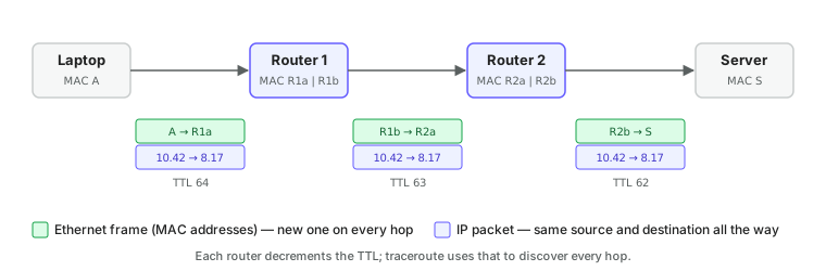
When a packet arrives, the router:
- Discards the Ethernet frame it arrived in.
- Reads the destination IP address.
- Finds the most specific matching entry in its routing table (the longest prefix match).
- Decrements the packet's hop counter (TTL). If it reaches zero, the packet is dropped and an ICMP "time exceeded" message goes back to the sender. This is what
tracerouteexploits. - Builds a fresh Ethernet frame addressed to the next hop's MAC address (learned via ARP on that interface) and sends it.
Every router does this independently. No router knows the whole path; each one only knows the next step. That is what makes the internet scale.
A typical routing table on a small site router looks like this:
| Destination | Next hop | Meaning |
|---|---|---|
192.168.10.0/24 | directly connected | The staff VLAN, reachable on a local interface |
192.168.20.0/24 | directly connected | The guest VLAN |
10.0.0.0/8 | 10.1.1.1 | The corporate WAN, via another router |
0.0.0.0/0 | 203.0.113.1 | Everything else, via the ISP (the default route) |
The default route is what makes "the internet" work from inside a site: anything that doesn't match a more specific entry goes to the ISP.
On a ReadyLinks switch the routing table is show ip routing-table (there is no show ip route). The switch's own default gateway is the optional third argument of the VLAN interface's ip address command; additional static routes are added in config mode.
GL-24xT-P600D# show ip routing-table
GL-24xT-P600D# configure terminal
GL-24xT-P600D(config)# ip route 10.50.0.0 255.255.0.0 10.0.10.254
GL-24xT-P600D(config)# ip route 10.60.0.0 255.255.0.0 10.0.10.254 metric 10
GL-24xT-P600D(config)# write#Switching vs routing, side by side
| Switching | Routing | |
|---|---|---|
| Operates at | Layer 2 | Layer 3 |
| Looks at | Destination MAC | Destination IP |
| Table is built by | Learning from source addresses automatically | Configuration, directly connected networks, or routing protocols |
| Unknown destination | Flood to all ports | Drop (or send to the default route) |
| Broadcasts | Forwarded | Blocked |
| Headers | Unchanged | Ethernet header replaced, TTL decremented |
| Scope | One broadcast domain | Between broadcast domains and across the internet |
A Layer 3 switch is simply a switch that can do both: it switches within each VLAN and routes between VLANs, usually at full wire speed. In most ReadyLinks deployments the GLx switch does the inter-VLAN routing and a separate firewall or ISP router handles the internet connection.
#Transport: getting data to the right program
Once a packet arrives at the right device, something has to deliver it to the right program. That is the job of the transport layer, and two protocols do nearly all of it:
- TCP establishes a connection, numbers every byte, acknowledges what arrived, and retransmits what didn't. Web pages, email, SSH, and file transfers all use TCP because they need every byte to arrive in order.
- UDP just sends. No connection, no acknowledgements, no retransmission. DNS, DHCP, NTP, video streaming, and voice calls use UDP because low latency matters more than perfect delivery, or because the application handles reliability itself.
Both protocols add a port number to each packet. The destination port identifies the program: 443 for HTTPS, 53 for DNS, 67/68 for DHCP, 22 for SSH. When the firewall rules page says a ReadyLinks switch needs "TCP 443 outbound", this is the port it means.
#Putting it together
| Step | Layer | What is examined | Where it happens |
|---|---|---|---|
| Application builds a request | 4+ | Hostname, URL | Endpoint |
| DNS lookup | 4+ | Hostname → IP | Endpoint asks the DNS server |
| Local or remote decision | 3 | Destination IP vs own subnet | Endpoint |
| ARP for next hop | 2 | IP → MAC | Endpoint broadcasts, neighbour replies |
| Frame sent | 2 | Destination MAC | Endpoint → switch |
| Switch forwards | 2 | MAC table | Switch |
| Router forwards | 3 | Routing table | Router, repeated per hop |
| Packet delivered to program | 4 | Port number | Destination endpoint |
Next: IP addressing covers how the addresses in this story are chosen and handed out.
Last updated October 5, 2026